Rotation type fluid injection device

A fluid injection and rotary technology, which is applied in heating methods, lighting and heating equipment, space heating and ventilation, etc., can solve problems such as low flexibility, difficulty in rotating fluid injection devices, and limited use of the environment, so as to achieve extended use The effect of longevity

Inactive Publication Date: 2018-05-08
宙斯流体系统(上海)有限公司
View PDF12 Cites 6 Cited by
  • Summary
  • Abstract
  • Description
  • Claims
  • Application Information

AI Technical Summary

Problems solved by technology

[0003] In view of the deficiencies in the prior art, the purpose of the present invention is to provide a rotary fluid injection de

Method used


Image

  • Rotation type fluid injection device
  • Rotation type fluid injection device
  • Rotation type fluid injection device

Examples


Embodiment 1

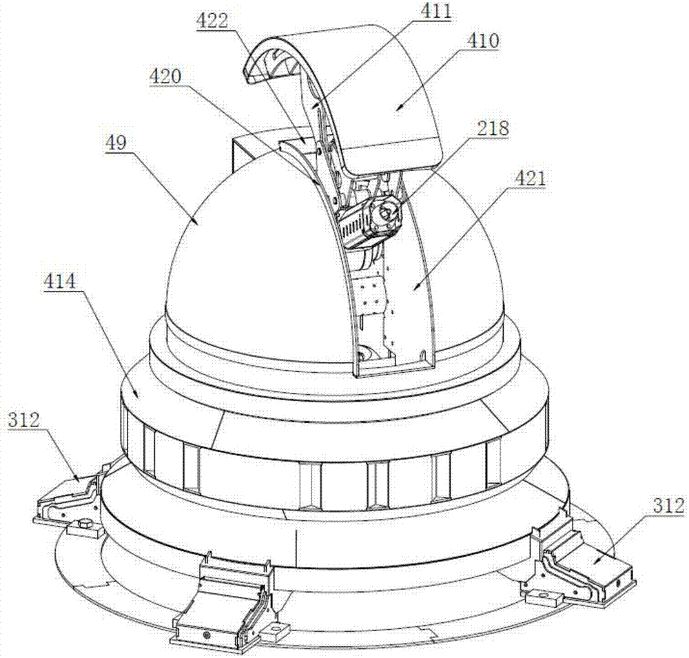
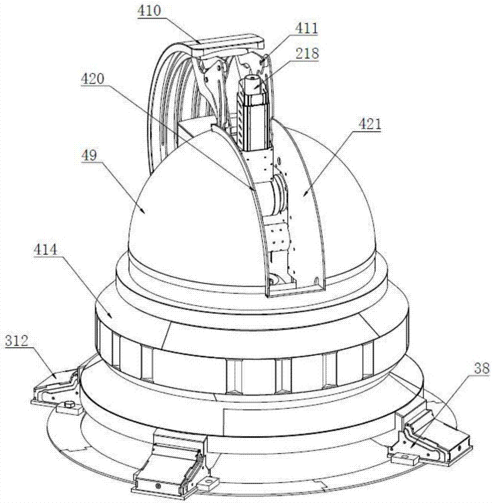
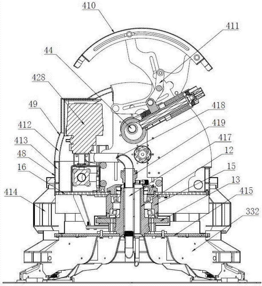
[0134] Embodiment 1: as Figure 1 to Figure 18 As shown, a rotary fluid injection device includes a rotary support mechanism, a fluid injection mechanism, and a fluid supply pipeline. The rotary support mechanism includes a base 11, a main shaft 12, a main gear 13, a driving gear 14, an oil cylinder housing 15, and a rotary platform 16 and a gear drive mechanism 17, the main shaft 12 is vertically arranged on the upper surface of the base 11, the main shaft 12 is provided with a main shaft through hole penetrating up and down, the main gear 13 is sleeved and fixed on the outside of the main shaft 12, the The oil cylinder housing 15 is sleeved on the outside of the main shaft 12 through the main bearing 18, the rotating platform 16 is sleeved and fixed on the oil cylinder housing 15, the driving gear 14 is meshed with the main gear 13, and the gear driving mechanism is set on the rotating platform 16, the gear drive mechanism is in transmission connection with the drive gear 14...

Embodiment 2

[0178] Embodiment 2, as a kind of improved scheme of embodiment 1, such as Figure 20 to Figure 22 As shown, the sliding shaft driving mechanism is a hydraulic sliding shaft driving mechanism, and the hydraulic sliding shaft driving mechanism includes a fixed shaft 314, a hydraulic cylinder 316, a coupling 318 and a hydraulic system 317, and the hydraulic system 317 is arranged on the bottom horizontal plate 31, the two ends of the fixed shaft 314 are respectively connected with the two lower support plates 32, the hydraulic system includes an oil storage tank, a hydraulic pump, a one-way valve and a reversing valve, the oil storage tank, hydraulic pump, The one-way valve and the reversing valve are connected in turn through the oil inlet pipeline, the oil storage tank and the reversing valve are connected through the oil return pipeline, the reversing valve and the hydraulic cylinder 316 are connected through two hydraulic pipelines, and the hydraulic cylinder 316 The cylinde...

Embodiment 3

[0181] Embodiment 3, as another kind of improved scheme of embodiment 1, such as Figure 23 and Figure 24 As shown, the sliding shaft driving mechanism is an electric sliding shaft driving mechanism, and the electric sliding shaft driving mechanism includes a leg driving motor controller 321, a leg driving motor 319, a connecting rod 320 and a link 318, and the legs The drive motor 319 is arranged on the bottom horizontal plate 31, the leg drive motor 319 is connected with the leg drive motor controller 321, the leg drive motor 319 is connected with one end of the connecting rod 320, the other end of the connecting rod 320 One end is connected with one end of the coupling part 318 , and the other end of the coupling part 318 is connected with the sliding shaft 35 , and the coupling part 318 is a bolt connecting the sliding shaft 35 and the connecting rod 320 . The controller and the leg drive motor controller 321 are connected through signal lines;

[0182]The outrigger dri...


PUM


Abstract

The invention discloses a rotation type fluid injection device, and belongs to the technical field of environment protection. The device comprises a rotation supporting mechanism, a fluid injection mechanism and a fluid supply pipeline. The rotation supporting mechanism comprises a base, a main shaft, a main gear, a drive gear, an oil cylinder shell, a rotation platform and a gear drive mechanism.The main shaft is vertically arranged on the upper surface of the base, and the main shaft is provided with an up-down penetrating main shaft through hole. The main gear sleeves and is fixed to the outer side of the main shaft, and the drive gear is engaged with the main gear. The gear drive mechanism and the drive gear are in transmission connection. The fluid injection mechanism comprises an injection gun barrel, a gun barrel supporting frame and a gun barrel drive mechanism, the gun barrel supporting frame is arranged on the rotation platform, the gun barrel drive mechanism is connected with the injection gun barrel, and the tail end of a fluid supply pipeline is connected with the injection gun barrel. By means of the rotation supporting mechanism, the injection gun barrel rotates inthe horizontal direction, the injection gun barrel rotates in the up-down direction through the gun barrel drive mechanism, the gun barrel injection range is enlarged, and the service life of the device is prolonged.

Description

technical field [0001] The invention belongs to the technical field of environmental protection, and in particular relates to a rotary fluid injection device. Background technique [0002] Existing fluid injection devices, such as fire water cannons installed next to chemical plant production equipment, generally only have the function of rotating up and down, not horizontally, and can only spray fluid in specific areas, with low flexibility. Its up and down rotation is adjusted by manpower, and the adjustment accuracy is low. When it is adjusted by manpower, the fluid injection device must be set at a position where personnel can easily reach and the operating environment is relatively safe, which greatly limits the scope of use of the device. Contents of the invention [0003] In view of the deficiencies in the prior art, the purpose of the present invention is to provide a rotary fluid injection device to solve the problems of difficult rotation, low flexibility and lim...

Claims


Application Information

Patent Timeline
IPC IPC(8): A62C31/03A62C31/28F24F3/16
CPCA62C31/03A62C31/28F24F3/16F24F8/30
Inventor 顾炎彬
Owner 宙斯流体系统(上海)有限公司
Why Eureka
Try Eureka