High-strength steel part hot-stamping forming device with gradient distributed performance

A technology of hot stamping and gradient distribution, applied in forming tools, metal processing equipment, metal processing, etc., to achieve the effect of reducing equipment cost, shortening production cycle, and shortening design cycle

Inactive Publication Date: 2018-05-08
JILIN UNIV
View PDF5 Cites 1 Cited by
  • Summary
  • Abstract
  • Description
  • Claims
  • Application Information

AI Technical Summary

Problems solved by technology

[0010] The present invention has designed and developed a high-strength steel part hot stamping forming device with gradient distribution of performance. The problem of hot stamping integral forming after transfer

Method used


Image

  • High-strength steel part hot-stamping forming device with gradient distributed performance
  • High-strength steel part hot-stamping forming device with gradient distributed performance
  • High-strength steel part hot-stamping forming device with gradient distributed performance

Examples


Embodiment 1

[0089] Zone cooling hot stamping

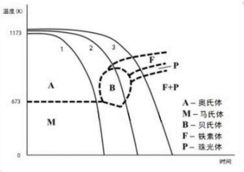
[0090] Such as Figure 21 As shown, the zoned cooling method is used to realize the situation that the front region (A region) of the thermoformed part is a martensitic phase, and the rear region (B region) is a mixed phase of ferrite and pearlite. A high-strength steel sheet 600 with a size of 1200mm×600mm×1.5mm and a material of 22MnB5 is used as the operation object, and is divided into two areas in the length direction.

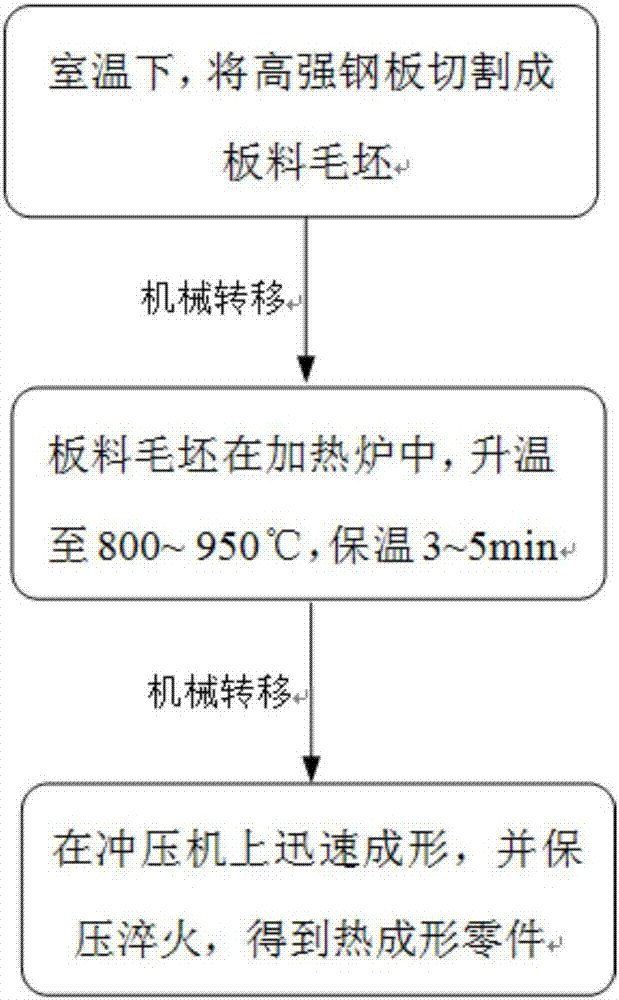
[0091] Proceed as follows:

[0092] 1. Use a cutting machine to cut a piece of high-strength steel sheet 600 with a size of 1200mm×600mm×1.5mm and a material of 22MnB5.

[0093] 2. The control system in the upper mold base 100 controls the upper mold mechanism to drive the upper fixed plate 120 and the upper six mold blocks (front mold blocks 510a, 510b, 510c, rear mold blocks 520a, 520b, 520c) to The front moves to the maximum position at a speed of 0.2m / s and stops.

[0094] 3. Place and position the cut high-stren...

Embodiment 2

[0102] Zone heating hot stamping

[0103] Such as Figure 21 As shown, the front region (A region) of the thermoformed part is a martensitic phase, and the rear region (B region) is a mixed phase of ferrite and pearlite by using a zoned heating method. A high-strength steel sheet 600 with a size of 1200mm×600mm×1.5mm and a material of 22MnB5 is used as the operation object, and is divided into two areas in the length direction.

[0104] Proceed as follows:

[0105] 1. Use a cutting machine to cut a piece of high-strength steel sheet 600 with a size of 1200mm×600mm×1.5mm and a material of 22MnB5.

[0106] 2. The internal control system of the upper mold base 1 controls the upper mold mechanism to drive the upper fixed plate 120 and the upper six mold blocks (the front mold blocks 510a, 510b, 510c, and the rear mold blocks 520a, 520b, 520c) to The front moves to the maximum position at a speed of 0.2m / s and stops.

[0107] 3. Place and position the cut high-strength steel sh...


PUM

PropertyMeasurementUnit
yield strengthaaaaaaaaaa

Abstract

The invention discloses a high-strength steel part hot-stamping forming device with gradient distributed performance. The high-strength steel part hot-stamping forming device with the gradient distributed performance comprises an upper die seat, an upper fixing plate, a plurality of upper die blocks, a lower die seat, a lower fixing plate and a plurality of lower die blocks; the upper fixing plateis mounted on the upper part of the upper die seat through a first air pressure device, the upper fixing plate is provided with an upper fixing plate protruding part and an upper fixing plate groovepart, and a second air pressure device is mounted on the upper fixing plate groove part; the multiple upper die blocks are fixedly connected with the upper fixing plate protruding part and the secondair pressure device correspondingly, and each upper die block is provided with a heating hole channel and a cooling water channel; the lower fixing plate is fixed to the upper part of the lower die seat, the lower fixing plate is provided with a lower fixing plate protruding part and a lower fixing plate groove part, and a third air pressure device is mounted on the lower fixing plate groove part;and the multiple lower die blocks are fixedly connected with the lower fixing plate protruding part and the third air pressure device correspondingly, and each lower die block is provided with a heating hole channel and a cooling water channel, wherein the upper fixing plate protruding part is matched with the lower fixing plate groove part.

Description

technical field [0001] The invention relates to the field of high-strength steel hot stamping forming, in particular to a hot stamping forming device for high-strength steel parts with performance gradient distribution. Background technique [0002] With the improvement of energy saving and emission reduction requirements, the lightweight design of the body has been paid more and more attention by the automobile industry. There are two main ways to realize the weight reduction of the car body: one is to reduce the weight of the structure, that is, to optimize the structure by combining finite element technology and optimization design method to improve the structure of the parts or reduce the number; the other is to reduce the weight of the material, that is, to use high Manufacture body structural parts with high-performance or lightweight materials, such as: high-strength steel, aluminum alloy, magnesium alloy, carbon fiber and other materials. In the current automobile m...

Claims


Application Information

Patent Timeline
Patent Type & Authority Applications(China)
IPC IPC(8): B21D22/02B21D37/10B21D37/16B21C51/00
CPCB21C51/00B21D22/02B21D37/10B21D37/16
Inventor 庄蔚敏王楠解东旋王志勇孙健李安琪王涛高瑞娟
Owner JILIN UNIV
Why Eureka
Try Eureka