A control method for seam tracking

A control method and welding torch technology, applied in the field of automatic welding sensing, can solve the problems of low versatility, single function, poor flexibility, etc.

Active Publication Date: 2020-01-14
XIANGTAN UNIV
View PDF7 Cites 0 Cited by
  • Summary
  • Abstract
  • Description
  • Claims
  • Application Information

AI Technical Summary

Problems solved by technology

[0006] The invention proposes a design idea of ​​a control method for seam tracking, which can not only obtain the left and right deviation between the center of the weld seam and the center of the molten pool to realize seam tracking, but also can be completed by swinging the visual sensor and switching the light reduction filter The guidance of the initial position of the weld and the planning of the weld trajectory make full use of the information that the visual sensor can obtain, and solve the problems of single function, low versatility and poor flexibility of the current visual sensor used for weld tracking

Method used


Image

  • A control method for seam tracking
  • A control method for seam tracking
  • A control method for seam tracking

Examples


Embodiment 1

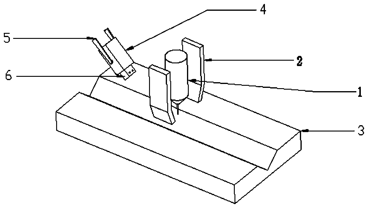
[0028] Example 1, such as figure 1 As shown, the first step: before the welding starts, the visual sensor 4 directly takes pictures of the workpiece 3 without adding a light-reducing filter, and the image processing is used to identify and guide the welding seam and the starting position of the welding And carry out the trajectory planning of the front distance welding torch for rough tracking.

[0029] Step 2: Swing the swing arm 5 to align the vision sensor 4 with the welding torch, and the upper position of the slider 1 22 is ready to acquire images during welding in real time.

[0030] Step 3: After starting welding, process the image collected by the visual sensor to obtain the deviation value between the center of the weld seam and the center of the molten pool, and then compare it with the left and right deviation value obtained by the magnetron arc sensor. When the threshold value is higher than the threshold value, the deviation information obtained by the visual sen...

Embodiment 2

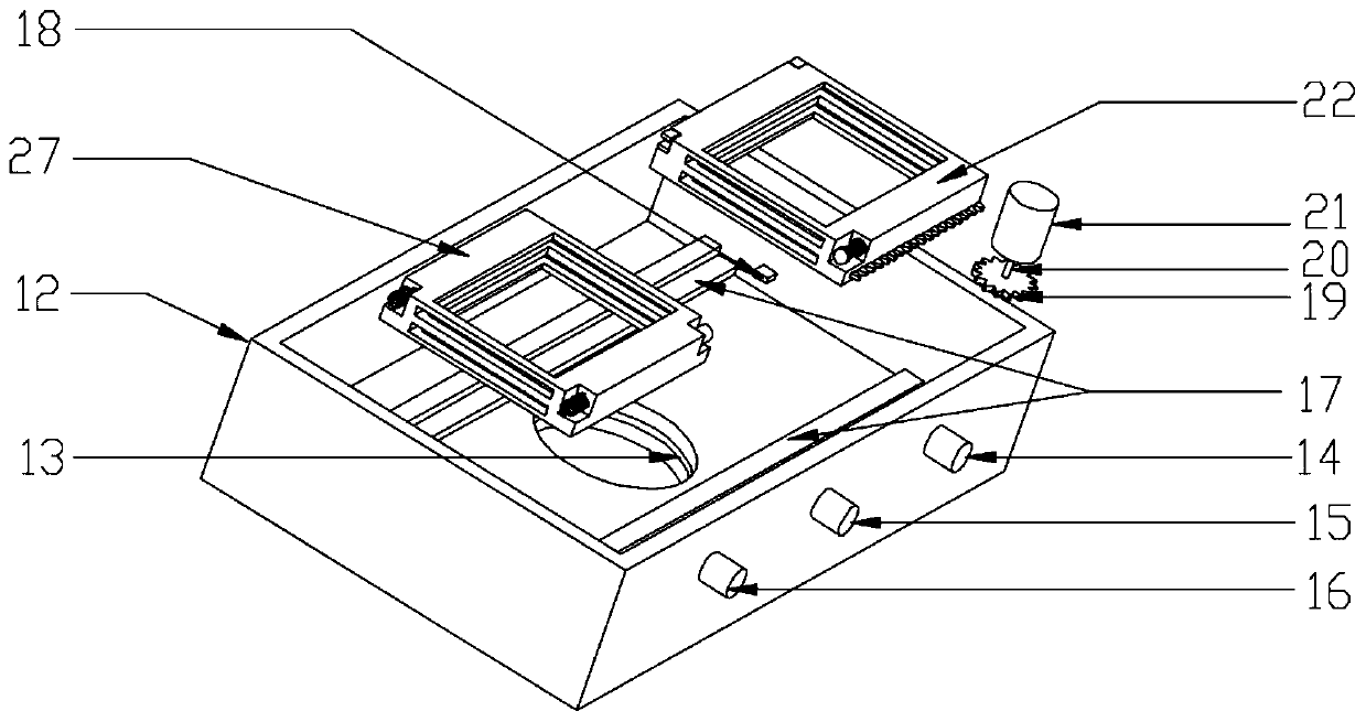
[0033] Example 2, such as Figure 2-Figure 7 , the slider one 22 and the slider two 27 move on the slide rail 17, and the slider one 22 drives the rotating gear 23 meshed with the transmission gear 19 through the transmission motor 21 to rotate and slide, and the slider two 27 The state of motion is jointly determined by the spring 30 and the electromagnet 24 on the slide block one 22.

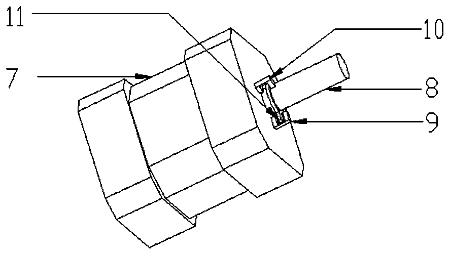
[0034] Described transmission motor 21 adopts photoelectric switch to control the on-off of relay to control the positive and negative rotation and start-stop of transmission motor, as Image 6 , 7 . Among them, the relay normally closed normally open contact SB 2 Controlled by the photoelectric switch one 9, when the light shield one 11 on the swing motor 7 turns to the photoelectric switch one 9 on it, the normally open contact SB 2 closed, normally closed contact SB 2 disconnected, the transmission motor 21 rotates forward, and at the same time Figure 7 The middle light-emitting diod...

Embodiment 3

[0035] Example 3, such as Figure 8 As shown, the electromagnet 24 uses photoelectric switch 2 10 and photoelectric switch 3 25 to control its on-off through the SR latch. When the shading plate 3 29 enters the photoelectric switch 25, the S terminal in the SR latch is set to 1, and the R terminal is still 0. At this time, Q is converted to Q=1, and the electromagnet 24 is energized, and the adsorption iron block 28 drives the slider 2 27 co-movements while Figure 8 Medium LED D 2 Conduction, the indicator light three 16 is on. When the swing motor 7 starts to move, it drives the light-shielding sheet one 11 on the rotating shaft one 8 to rotate to the photoelectric switch two 10. At this moment, the R terminal is set to 1, the S terminal is 0, Q is converted to Q=0, the electromagnet is powered off, and the slide block The second 27 resets under the action of the spring 30, and the indicator light three 16 goes out at the same time, making full use of the holding, setting...


PUM


Abstract

The invention discloses a vision sensing device for welding seam tracking. The vision sensing device for welding seam tracking is used for jointly achieving automatic tracking of welding seams with amagnetic control arc sensor. Before welding starts, a vision sensor acquires an image of a to-be-welded workpiece under the condition that optical filters for light are not increased or decreased, andrecognizing and guiding of the welding initial position and planning of the welding gun trajectory are completed. Next, the vision sensor is made to swing to be aligned with a welding gun, at the moment, a slider 1 is automatically loaded to a light passing hole, the left and right deviation information during welding starts to be acquired, a deviation signal acquired by the magnetic control arcsensor is used for joint correction to achieve welding seam tracking, after the welding gun trajectory path acquired at the beginning is completed, it is needed to swing the vision sensor again so asto acquire a front weldment image, in the process from that the vision sensor is aligned with the welding gun to swing to that the vision sensor is perpendicular to a workpiece, a slider 2 is automatically loaded to the light passing hole to perform continuous sampling on the weldment image, the accurate welding seam image is acquired by means of image treatment, the accurate welding seam image and the deviation information acquired by the magnetic control arc sensor are used for joint accurate tracking, and automatic welding is completed.

Description

Technical field: [0001] The invention relates to a control method for seam tracking and belongs to the technical field of automatic welding sensing. Background technique [0002] The tracking accuracy and stability of complex welds such as curved lines and folded lines and angles are low, and the information obtained by a single sensor can only reflect certain aspects of the welding process. The complete information is incomplete, and it is difficult to guarantee the accuracy and reliability of the input information, so it is impossible to accurately complete the automatic tracking of the weld. [0003] At present, most of the visual sensors used in the field of automatic seam tracking basically only have a set of light reduction filters, so they can only obtain weld images under a single condition. The main function is to obtain the distance between the center of the weld and the center of the molten pool. Left and right deviation to realize seam tracking. However, there ...

Claims


Application Information

Patent Timeline
Patent Type & Authority Patents(China)
IPC IPC(8): B23K9/127B23K9/133
CPCB23K9/1276B23K9/133
Inventor 洪波李伟鹏谭炽泉王英俊贾爱亭
Owner XIANGTAN UNIV
Why Eureka
Try Eureka