
Assembly-type cast-in-place concrete structure disassembly-free template pipe gallery

A technology for concrete structures and formwork-free dismantling, which is applied to underwater structures, infrastructure engineering, water conservancy projects, etc., can solve the problems of uneven foundation resistance, unfavorable ecological environment protection, water-stop belt cracking, etc., and achieves improved construction. Speed ​​and construction accuracy, the effect of reducing natural resource consumption and increasing construction speed

Pending Publication Date: 2018-05-08
HARBIN HONGSHENG ROOM ENERGY SAVING SYST RES CENT
View PDF0 Cites 3 Cited by
  • Summary
  • Abstract
  • Description
  • Claims
  • Application Information

AI Technical Summary

Problems solved by technology

Limited by site conditions, the time period is long, and the impermeability of the concrete produced on site is not as good as that produced in the factory, so local leakage is easy to occur, and construction cracks are prone to appear in the culvert pipe, and the side wall of the culvert body is cracked, etc.
[0004] The on-site box culvert sections are connected by rubber waterstops. The disadvantage is that the ability to resist uneven subsidence of the foundation is poor, and the interface is prone to vertical dislocation and deformation, resulting in cracking of the waterstops. Cast-in-place construction requires space for the formwork , the amount of earthwork increases, and the damage to the surrounding environment is also great, which is not conducive to the protection of the ecological environment

Method used


Image

  • Assembly-type cast-in-place concrete structure disassembly-free template pipe gallery
  • Assembly-type cast-in-place concrete structure disassembly-free template pipe gallery
  • Assembly-type cast-in-place concrete structure disassembly-free template pipe gallery

Examples


Embodiment Construction

[0027] The present invention will be described in more detail below with examples in conjunction with the accompanying drawings.

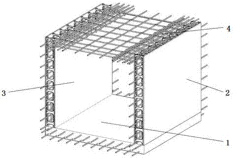
[0028] combine figure 1 , The first embodiment of the present invention includes a cast-in-place concrete base 1 , two prefabricated non-demolition formwork system wall panels 2 , 3 and a prefabricated non-demolition floor panel 4 .

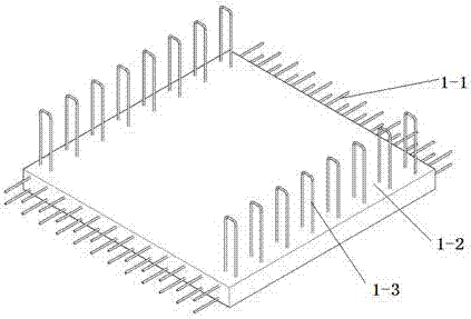
[0029] combine figure 2 , the cast-in-place concrete floor specifically includes bottom reinforcement 1-1, poured concrete layer 1-2 and reserved wall anchorage reinforcement 1-3 on both sides, and the wall anchorage reinforcement is preferably n-type.

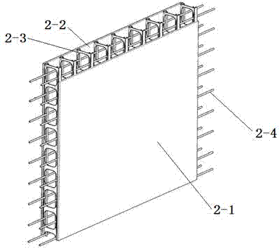
[0030] combine image 3 , the prefabricated no-demolition formwork system wall panel specifically includes a metal truss composed of section steel 2-3 and steel bars 2-4, a no-demolition formwork 2-2 installed on the outside of the metal truss, and a no-demolition formwork 2-1 installed on the inside of the metal truss . The demolition-free formwork is fixed on t...


PUM


Abstract

The invention provides an assembly-type cast-in-place concrete structure disassembly-free template pipe gallery. The pipe gallery comprises a cast-in-place concrete bottom plate, two prefabricated disassembly-free template system wallboards and a prefabricated disassembly-free floor board; wall anchoring steel bars are reserved on the two sides of the cast-in-place concrete bottom plate; each prefabricated disassembly-free template system wallboard comprises a metal truss and disassembly-free templates arranged on the two sides of the corresponding metal truss; the prefabricated disassembly-free floor board comprises a bottom face disassembly-free template and a steel bar net arranged on the bottom face disassembly-free template; and the two prefabricated disassembly-free template system wallboards are vertically arranged on the two sides of the cast-in-place concrete bottom plate, the prefabricated disassembly-free floor board is arranged at the tops of the two prefabricated disassembly-free template system wallboards, pouring concrete bearing walls are arranged in gaps between disassembly-free templates of the prefabricated disassembly-free template system wallboards, and a pouring concrete top layer is arranged on the prefabricated disassembly-free floor board. The main structure of the pipe gallery is completed in a factory form outside the construction site, assembling iscarried out in the construction site, the construction speed of the pipe gallery is increased, and the construction difficulty is reduced.

Description

technical field [0001] The invention relates to an underground pipe gallery, in particular to an assembled underground pipe gallery. Background technique [0002] The underground comprehensive pipe gallery is a structure and ancillary facilities built underground to accommodate various urban engineering pipelines. [0003] The underground pipe gallery is divided into main line pipe gallery, branch line pipe gallery and cable pipe gallery according to the type. The construction method of the underground pipe gallery depends on the cost and the feasibility of implementation. The main line pipe gallery usually adopts the slotting method and cast-in-place construction method due to its large cross-section, self-heavy weight, and large engineering volume. The slotting method is used for construction, which cannot meet the requirements of pipe jacking. Construction is not possible in rainy days and in winter in northern regions. The construction time is long, and the workload o...

Claims


Application Information

Patent Timeline
IPC IPC(8): E02D29/045
CPCE02D29/10
Inventor 林国海翟洪远林宣佐
Owner HARBIN HONGSHENG ROOM ENERGY SAVING SYST RES CENT
Learn More