Self-air-entrainment-based plasma jet igniter of aero-engine

An aero-engine and plasma technology, which is applied to machines/engines, gas turbine devices, mechanical equipment, etc., can solve the problems of heavy weight, large volume, complex structure, etc. Effect

Active Publication Date: 2018-05-08
AIR FORCE UNIV PLA
View PDF7 Cites 21 Cited by
  • Summary
  • Abstract
  • Description
  • Claims
  • Application Information

AI Technical Summary

Problems solved by technology

However, in the above two Chinese invention patents, the plasma jet igniter needs an external air-entraining device, which has a relatively complicated structure, large volume and heavy weight

Method used


Image

  • Self-air-entrainment-based plasma jet igniter of aero-engine
  • Self-air-entrainment-based plasma jet igniter of aero-engine
  • Self-air-entrainment-based plasma jet igniter of aero-engine

Examples


Embodiment 1

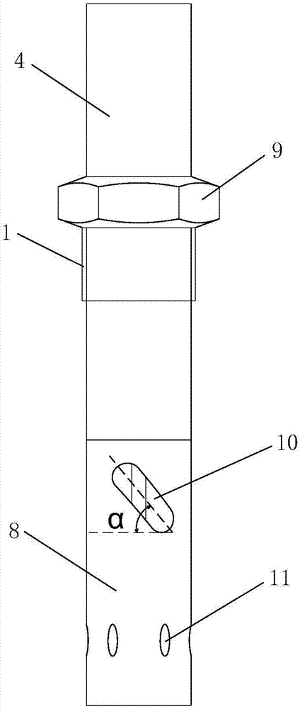
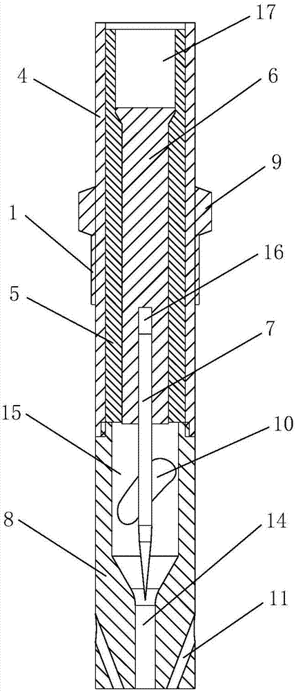
[0046] Such as Figure 1 to Figure 5 The shown aero-engine plasma jet igniter based on self-bleed air includes an outer tube 4, an insulating inner tube 5, a conductive copper tube 6, a cathode 7 and an anode 8, and the outer tube 4 is arranged above the anode 8 , the lower end of the outer tube 4 is fixedly connected to the upper end of the anode 8, the insulating inner tube 5 is set in the outer tube 4, the insulating inner tube 5 is a hollow rotating body, and the conductive copper tube 6 is set in the insulating inner tube 5, the head of the conductive copper tube 6 and the head of the insulating inner tube 5 form a stepped matching structure, and the tops of the outer tube 4, the insulating inner tube 5 and the conductive copper tube 6 jointly form a power connection interface 17, The bottom of the conductive copper tube 6 is provided with a groove 16 with an internal thread on the inner wall, and the top of the cathode 7 is screwed to the groove 16. The outer tube 4, the...

Embodiment 2

[0064] Such as Figure 6 to Figure 8 As shown, the difference between this embodiment and Embodiment 1 is that the air inlet 10 of the igniter is a chute structure, and the air inlet 10 of the igniter is in the shape of a vane. In this embodiment, the structures, connections and working principles of other parts are the same as those in Embodiment 1.

Embodiment 3

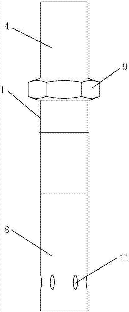
[0066] Such as Figure 9 to Figure 11 As shown, the difference between this embodiment and Embodiment 1 is that: the air inlet 10 of the igniter is composed of a plurality of meshes arranged in a rectangular array; the angle between the meshes and the horizontal plane is 0°.

[0067] In this embodiment, the structures, connections and working principles of other parts are the same as those in Embodiment 1.


PUM


Abstract

The invention discloses a self-air-entrainment-based plasma jet igniter of an aero-engine. The plasma jet igniter comprises an outer pipe, an insulating inner pipe, a conducting copper pipe, a cathodeand an anode; the lower end of the outer pipe is fixedly connected with the upper end of the anode; the outer pipe is internally sleeved with the insulating inner pipe; the insulting inner pipe is internally sleeved with the conducting copper pipe; the upper part of the cathode has threaded connection with a groove formed in the lower part of the conducting copper pipe; a hollow structure insidethe upper part of the cathode is an ionization region; the hollow structure inside the lower part of the anode is a flow jet region; the outer sidewall of the ionization region is provided with an igniter air inlet for leading air which is inside a main combustion chamber or mixed rotational air flow which is inside an afterburner into the ionization region; the upper part of the cathode is positioned inside the conducting copper pipe; and the lower part of the cathode is positioned inside the ionization region. The plasma jet igniter disclosed by the invention needs not to be externally connected with an air entraining device; the air flow in two channels of the main combustion chamber or the air flow in the afterburner is directly led into the plasma jet igniter, so the structure of an igniting device is simplified, and the weight and volume of the igniting device are reduced.

Description

technical field [0001] The invention belongs to the technical field of aero-engines, in particular to an aero-engine plasma jet igniter based on self-bleed air. Background technique [0002] At present, there are ignition devices in the main combustion chamber and the afterburner of the aero turbine engine. The ignition method used in the main combustion chamber is electric nozzle ignition; Thermal jet ignition and catalytic ignition, various ignition methods have certain limitations. The ignition devices of the main combustion chamber and the afterburner respectively have the following main problems: [0003] The problems of the ignition device in the main combustion chamber are as follows: (1) The electric nozzle ignition is directly ignited by the electric spark generated by the high-energy electric nozzle, the energy is small, and the ignition core area is small; especially in high altitude conditions, the ignition envelope is small , the ignition success rate is low, ...

Claims


Application Information

Patent Timeline
Patent Type & Authority Applications(China)
IPC IPC(8): F02C7/266
CPCF02C7/266
Inventor 于锦禄何立明丁未黄丹青王思博秦建飞胡雅骥金涛
Owner AIR FORCE UNIV PLA
Why Eureka
Try Eureka