Vacuum pipe clamp valve applied to vacuum system and control method of vacuum pipe clamp valve

A vacuum system and vacuum tube technology, applied in the direction of diaphragm valves, valve devices, engine components, etc., to achieve the effect of ensuring sealing, ensuring normal operation, and saving installation space

Active Publication Date: 2018-05-08
湖南真创环保科技有限公司
View PDF17 Cites 20 Cited by
  • Summary
  • Abstract
  • Description
  • Claims
  • Application Information

AI Technical Summary

Problems solved by technology

[0008] The pinch valves in the above patent documents all use compressed air to drive the opening and closing. Therefore, if the pinch valves in the above patent documents are applied to a vacuum system, the above problems will also exist

Method used


Image

  • Vacuum pipe clamp valve applied to vacuum system and control method of vacuum pipe clamp valve
  • Vacuum pipe clamp valve applied to vacuum system and control method of vacuum pipe clamp valve
  • Vacuum pipe clamp valve applied to vacuum system and control method of vacuum pipe clamp valve

Examples


Embodiment

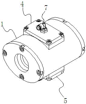
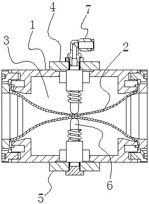
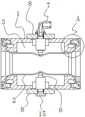
[0029] Example: such as Figure 1 to Figure 3 As shown, a vacuum pipe pinch valve applied to a vacuum system includes a pinch valve pipe body 1 and a sleeve 2 arranged inside the pinch valve pipe body 1, between the inner wall of the pinch valve pipe body 1 and the outer wall of the sleeve 2 Set as a sealed space 3, on the outer side of the pinch valve body 1, there are also elastic pressing block device one 4 and elastic pressing block device two 5, elastic pressing block device one 4 and elastic pressing block device two 5 The pressure block 6 extends into the sealed space 3 and clamps the sleeve 2 closed by the pressure block 6 in the elastic pressure block device 1 and the pressure block 6 in the elastic pressure block device 2, and the sleeve 2 is clamped in the pinch valve body 1 The outer part is also provided with a vacuum tube interface 7 for evacuating the sealed space. When the sealed space 3 is evacuated through the vacuum tube interface 7, the pressure block 6 of t...


PUM


Abstract

The invention discloses a vacuum pipe clamp valve applied to a vacuum system and a control method of the vacuum pipe clamp valve. The vacuum pipe clamp valve comprises a clamp valve pipe body and a casing pipe. A seal space is formed between the inner wall of the clamp valve pipe body and the outer wall of the casing pipe. A first elastic pressing block device and a second elastic pressing block device are arranged at the outer side of the clamp valve pipe body. A pressing block of the first elastic pressing block device and a pressing block of the second elastic pressing block device extend into the seal space, and the casing pipe is clamped and closed through the pressing block in the first elastic pressing block device and the pressing block in the second elastic pressing block device.A vacuum pipe interface is further arranged at the outer side of the clamp valve pipe body, wherein the vacuum pipe interface is used for conducting vacuum extraction on the seal space. After the sealspace is extracted to be in the vacuum state through the vacuum pipe interface, the pressing block of the first elastic pressing block device and the pressing block of the second elastic pressing block device retract to loosen clamping of the casing pipe, so that the casing pipe is opened. By means of the vacuum pipe clamp valve, it is not needed to additionally arrange an air compression systemto control the pipe clamp valve to be switched on and off; production cost is lowered; and reliability is high.

Description

Technical field [0001] The invention relates to a pipe clamp valve and a control method thereof, in particular to a vacuum pipe clamp valve applied to a vacuum system and a control method thereof. Background technique [0002] The pinch valve is also called the pinch valve, air bag valve, pinch-off valve, etc. in China. It uses pneumatic, electric, manual or hydraulic driving methods to squeeze the casing to switch or adjust. The pinch valve has a wide range of uses and can be used in many fields such as paper mills, pulp mills, electronics industry, food industry, cement, sand, glass and industrial sewage treatment plants. [0003] Among them, the pneumatic pinch valve is a new type of valve improved on the basis of the manual pinch valve in order to meet the special requirements of customers. It consists of upper and lower cast iron, cast steel valve bodies, rubber sleeves, large and small valve stems, gates, upper and lower guide posts, Pneumatic device and other parts. [0004]...

Claims


Application Information

Patent Timeline
Patent Type & Authority Applications(China)
IPC IPC(8): F16K7/04F16K7/06
CPCF16K7/04F16K7/06
Inventor 刘宇奇杨桂华赵海龙胡新旺
Owner 湖南真创环保科技有限公司
Why Eureka
Try Eureka