Device and method for measuring symmetry of rudder shaft slot of rudder shaft part
A detection device and detection method technology, applied in the direction of measuring devices, mechanical devices, mechanical measuring devices, etc., can solve the problems of high cost, occupying measuring equipment, affecting production progress, etc., achieve low cost, easy operation, and improve processing efficiency Effect
- Summary
- Abstract
- Description
- Claims
- Application Information
AI Technical Summary
Problems solved by technology
Method used
Image
Examples
Embodiment 1
[0027] The rudder shaft groove structure of rudder shaft parts is as follows: figure 1 shown.
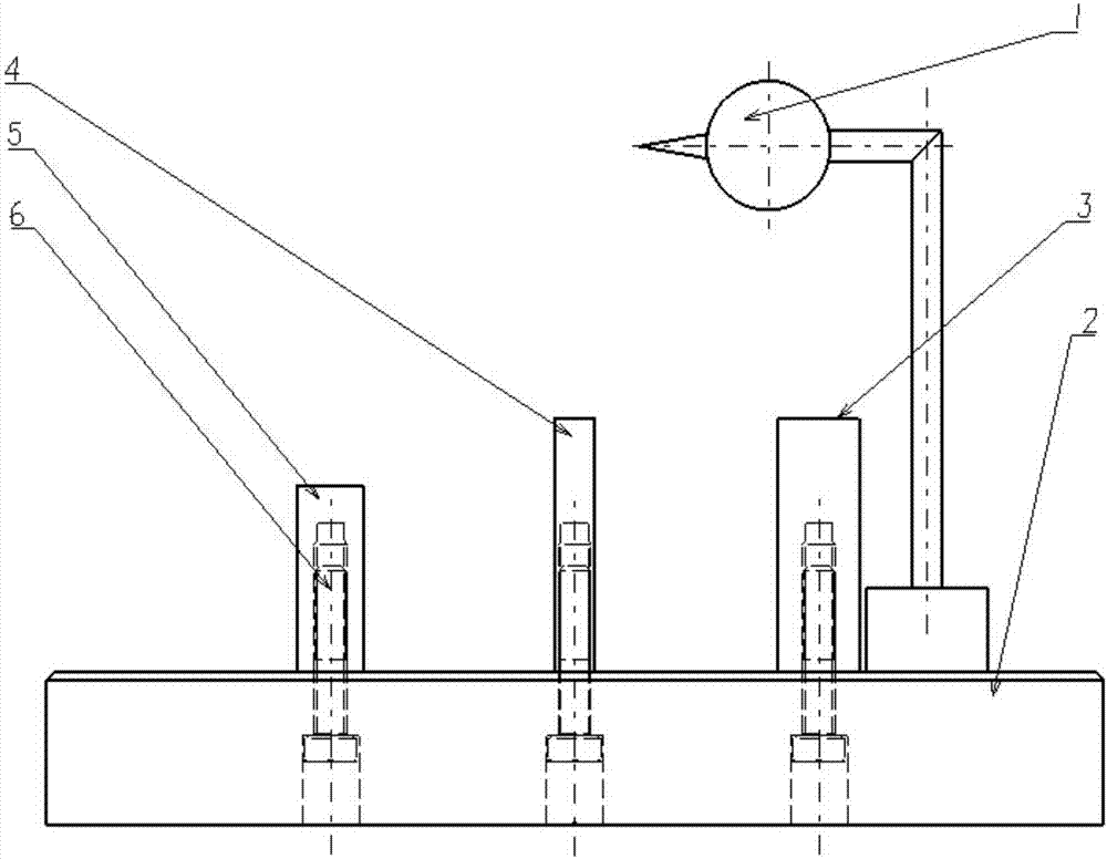
[0028] Such as figure 2 As shown, a device for detecting the symmetry of the rudder shaft groove of the rudder shaft parts according to the present invention includes a base 2, and the gauge block 1 3 and the gauge block 2 4 are connected side by side by connecting screws 6 above the base 2 , gauge block three 5; dial gauge 1 is magnetically adsorbed on the base 2, and is set near gauge block one 3, gauge block two 4, or gauge block three 5 as required during measurement; said gauge one 3, gauge Block two 4, measuring block three 5 are set for the rudder shaft 8 adapting to different groove widths, can dismantle.
[0029] The height of the contacts of the dial indicator 1 can be adjusted so that the contacts contact the tapered surfaces of the rudder shaft 8 at different heights.
[0030] The dimensions of the gauge block one 3, gauge block two 4, and gauge block three 5 can be ...
Embodiment 2
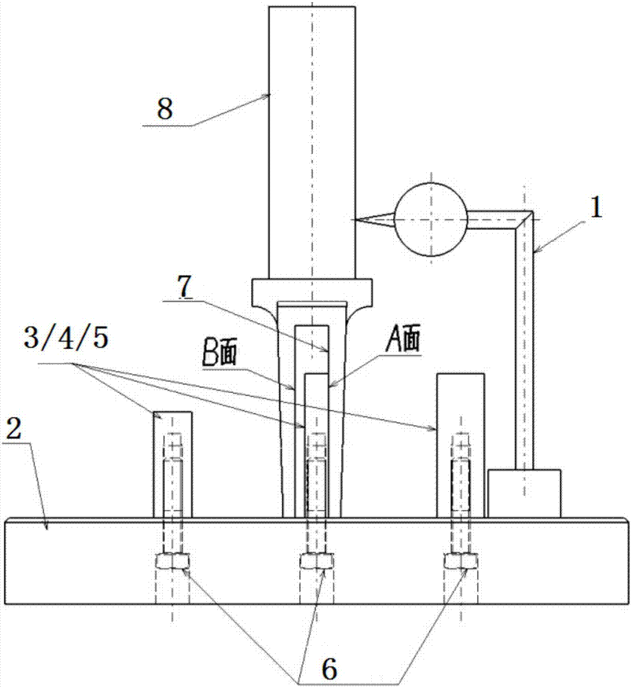
[0034] Such as figure 2 As shown, the method for detecting the symmetry of the rudder shaft groove of the rudder shaft part using the rudder shaft part rudder shaft groove symmetry detection device described in Embodiment 1 comprises the following steps:
[0035] Step (a), when measuring, make a side A in the rudder shaft groove 7 of the rudder shaft parts close to one of the gauge block 1 3, the gauge block 2 4 or the gauge block 3 5;
[0036] Step (b), adjust the position of the contact of dial indicator 1 on the base 2, make the contact of dial indicator 1 touch the cone surface of rudder shaft 8, move the rudder shaft 8 along the surface of the gauge block, and record the maximum reading of dial indicator 1;
[0037] Step (c), turning the rudder shaft 8 so that the other side B in the rudder shaft groove 7 is close to one of gauge block 1 3, gauge block 2 4 or gauge block 3 5;
[0038] Step (d), adjust the position of the contact of dial indicator 1 on the base 2 so that...
Embodiment 3
[0041] Such as figure 2 As shown, the method for detecting the symmetry of the rudder shaft groove of the rudder shaft part using the rudder shaft part rudder shaft groove symmetry detection device described in Embodiment 1 comprises the following steps:
[0042] Step (a), when measuring, make a side A in the rudder shaft groove 7 of the rudder shaft parts close to one of the gauge block 1 3, the gauge block 2 4 or the gauge block 3 5;
[0043] Step (b), adjust the position of the contact of dial indicator 1 on the base 2, make the contact of dial indicator 1 touch the cone surface of rudder shaft 8, move the rudder shaft 8 along the surface of the gauge block, and record the maximum reading of dial indicator 1;
[0044] Step (c), turning the rudder shaft 8 so that the other side B in the rudder shaft groove 7 is close to one of gauge block 1 3, gauge block 2 4 or gauge block 3 5;
[0045] Step (d), adjust the position of the contact of dial indicator 1 on the base 2 so that...
PUM
 Abstract
Description
Claims
Application Information
 - R&D
- Intellectual Property
- Life Sciences
- Materials
- Tech Scout
- Unparalleled Data Quality
- Higher Quality Content
- 60% Fewer Hallucinations
Browse by: Latest US Patents, China's latest patents, Technical Efficacy Thesaurus, Application Domain, Technology Topic, Popular Technical Reports.
© 2025 PatSnap. All rights reserved.Legal|Privacy policy|Modern Slavery Act Transparency Statement|Sitemap|About US| Contact US: help@patsnap.com


