A comprehensive deformation monitoring system and its application method
A deformation monitoring and monitoring device technology, applied in measuring devices, using optical devices, instruments, etc., can solve the problem that monitoring methods are not automated and intelligent, and reduce workload and physical labor. Dependence, the effect of improving stability
- Summary
- Abstract
- Description
- Claims
- Application Information
AI Technical Summary
Problems solved by technology
Method used
Image
Examples
Embodiment 1
[0071] This embodiment mainly introduces the composition of a deformation monitoring comprehensive system of the present invention.
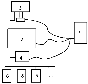
[0072] as attached figure 1 As shown, a comprehensive deformation monitoring system includes a central processing unit 2 , a display device 3 , a communication device 4 , a power supply 5 , and several monitoring devices 6 .
[0073] The central processing unit 2 is the core component of the whole system, at least including a data processing unit and an early warning unit. The data processing unit is used for processing the data collected by the monitoring device. The early warning unit is used to generate a corresponding early warning signal according to the processing result of the data processing unit, display it through the display device 3, and act on the alarm unit provided according to needs.
[0074] As an option, corresponding to the early warning unit of the central processing unit 2 , an audible and visual alarm unit is provided on ...
Embodiment 2
[0088] This embodiment is carried out on the basis of the foregoing embodiment 1, and mainly introduces a specific implementation manner of a monitoring device of a comprehensive deformation monitoring system of the present invention.
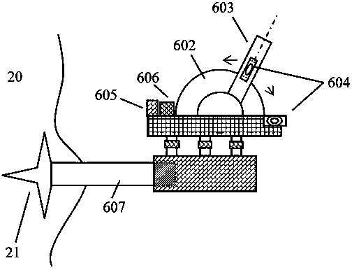
[0089] as attached figure 2 As shown, the main structure of the monitoring device is installed at the measurement position through a bracket, and the main structure includes a connecting base. The connection base includes a lower part, a middle part and an upper part.
[0090] The lower part of the connection base is fixedly connected to the bracket. As an option, the connection method may be threaded, for example, the bracket includes external threads, and the lower part of the connection base includes internal threads that match the external threads on the bracket.
[0091] as attached figure 2As shown, a laser rangefinder, an angle sensor, a wireless signal transceiver, data acquisition and a controller are arranged on the upper part of ...
Embodiment 3
[0098] This embodiment is carried out on the basis of the foregoing embodiment 1 or 2, and mainly introduces a support structure of a comprehensive deformation monitoring system of the present invention.
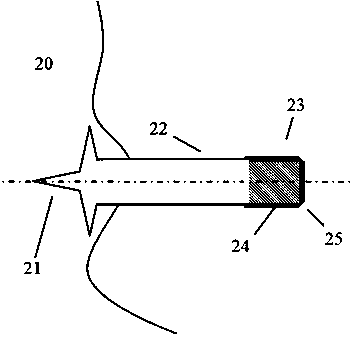
[0099] combined with image 3 It can be seen that the bracket 607 is in the shape of a rod as a whole, including the fixed end 21, the rod portion 22, and the connecting end 23 connected in sequence; the bracket is fixed in the concrete wall 20 through the "claw"-shaped fixed end 21, The concrete wall is cast on site, and the "claw"-shaped fixed end 21 is firmly combined into the concrete wall 20 . The rod portion 22 is a cylindrical rod. The bracket is made of anti-corrosion, anti-rust metal. The surface of the connecting end 23 is an external thread 24 . The position near the outer edge of the connecting end 23 is a chamfer 25 . The chamfer 25 is a circle of oblique shape, in order to facilitate screwing the nut on the external thread, and also to facilitate the buckle...
PUM
 Abstract
Description
Claims
Application Information
 - R&D
- Intellectual Property
- Life Sciences
- Materials
- Tech Scout
- Unparalleled Data Quality
- Higher Quality Content
- 60% Fewer Hallucinations
Browse by: Latest US Patents, China's latest patents, Technical Efficacy Thesaurus, Application Domain, Technology Topic, Popular Technical Reports.
© 2025 PatSnap. All rights reserved.Legal|Privacy policy|Modern Slavery Act Transparency Statement|Sitemap|About US| Contact US: help@patsnap.com


