Assembled steel beam overall stability testing concentrated load loading device and method

A technology of stability test and concentrated load, which is applied in the direction of measuring device, using stable tension/pressure to test the strength of materials, instruments, etc. The problem that the device cannot be solved, etc., achieves the effect of reducing the load action area, wide applicability of the section, and convenient positioning

Pending Publication Date: 2018-05-08
SHENYANG JIANZHU UNIVERSITY
View PDF14 Cites 6 Cited by
  • Summary
  • Abstract
  • Description
  • Claims
  • Application Information

AI Technical Summary

Problems solved by technology

At present, there are few tests on the stability of steel beams at home and abroad, mainly because of the problems that cannot be solved by the loading device
In the few existing stability tests, jacks are often used to apply concentrated loads, and jack loading also has significant disadvantages: when traditional jacks apply concentrated loads, when the steel beams buckle due to bending and twisting, the position of the loading point will shift, and the loading The direction is no longer vertically downward. As the deformation increases, the jack will break away from the surface of the specimen, resulting in the termination of the test; the top of the jack is a disc, and the surface load is applied, which deviates from the ideal concentrated load.
Since the loading ring is an in-plane structure rather than a spatial structure system, it is difficult to ensure the stability in the plane of the steel beam, that is, the verticality of the loading direction is not easy to control

Method used


Image

  • Assembled steel beam overall stability testing concentrated load loading device and method
  • Assembled steel beam overall stability testing concentrated load loading device and method
  • Assembled steel beam overall stability testing concentrated load loading device and method

Examples


Embodiment Construction

[0034] The present invention will be described in further detail below in conjunction with embodiment.

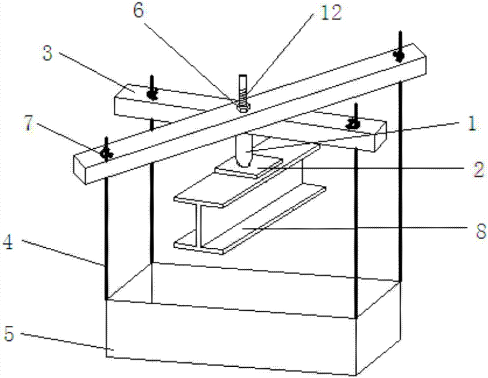
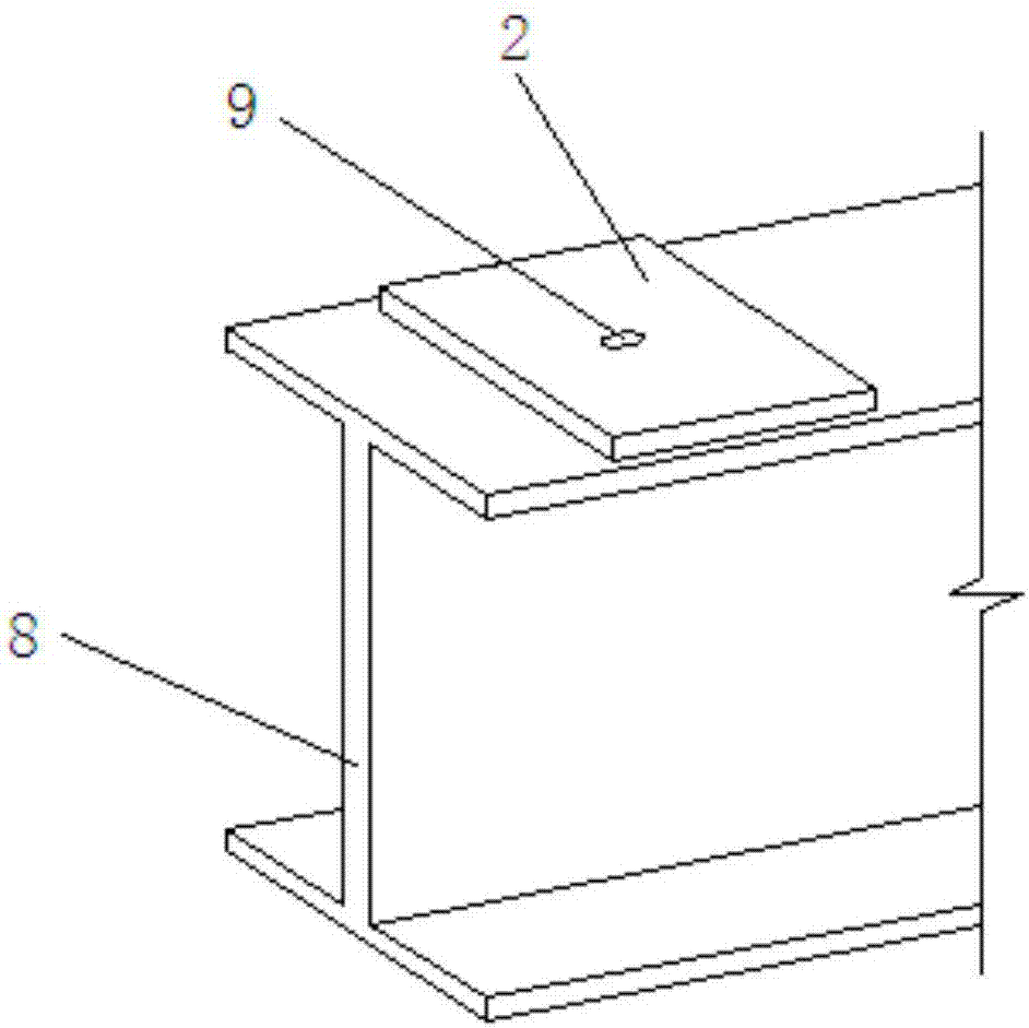
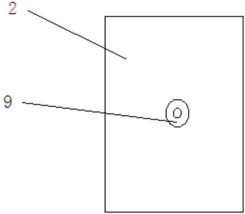
[0035] according to Figure 1 ~ Figure 2As shown, a kind of assembly-type steel beam overall stability test concentrated load loading device provided by the present invention comprises a loading taper nail 1, a loading plate 2, a square steel pipe 3, a steel strand 4 and a loading box 5, two square steel pipes 3 are overlapped and superimposed to form a cross shape, and the angle between the two square steel pipes 3 can be adjusted as required, and a first through hole (not shown) is provided at the overlap of the two square steel pipes 3, And the square steel pipe 3 is a hollow steel pipe, the loading cone nail 1 is inserted in the first through hole, the first through hole is a circular through hole, and its diameter is larger than the end of the loading cone nail 1 diameter, so that the end of the loading taper 1 can fully extend into the first through hole, the outer w...


PUM


Abstract

The invention discloses an assembled steel beam overall stability testing concentrated load loading device and method. The method comprises a loading conical screw, a loading plate, square steel tubes, steel strands and loading tanks, wherein two square steel tubes are in mutual lap joint in a cross manner; the loading conical screw is inserted into a lap joint part of the two square steel tubes;threads are formed in the outer wall of the loading conical screw; the square steel tubes are locked by a screw nut screwed on the threads; the loading tanks are hung at four end parts of the square steel tubes through the steel strands respectively; a steel beam to be tested is fixedly connected below the loading plate; an end part of the loading conical screw penetrates through a through hole inthe loading plate and is in contact with the steel beam to be tested. The loading device is convenient in material obtaining, simple and easy to manufacture, high in reusability and high in assembling degree, a series of problems caused by welding in a conventional loading device are avoided, the loading conical screw is convenient to replace and simple to operate, loading directions and positions are not changed, the action area of a load is reduced to the maximum extent, and an ideal state that a concentrated load is loaded to an action point is approximately achieved.

Description

Technical field: [0001] The invention relates to the technical field of steel structures, in particular to a concentrated load loading device and method for an overall stability test of an assembled steel beam. Background technique: [0002] The stability of the steel girder, the main stress member in the steel structure, has always been the focus of attention of researchers and designers. The concentrated load on the beam is a common situation in the actual stress of the component, so it is necessary to study the stability of the steel beam under the concentrated load. At present, there are few tests on the stability of steel beams at home and abroad, mainly because of the problems that cannot be solved by the loading device. In the few existing stability tests, jacks are commonly used to apply concentrated loads, and jack loading also has significant disadvantages: when the traditional jacks apply concentrated loads, the position of the loading point will shift when the s...

Claims


Application Information

Patent Timeline
Patent Type & Authority Applications(China)
IPC IPC(8): G01N3/14G01N3/02
CPCG01N3/02G01N3/14G01N2203/0033G01N2203/0003G01N2203/0019G01N2203/0075G01N2203/0264
Inventor 张壮南岳思哲王春刚
Owner SHENYANG JIANZHU UNIVERSITY
Why Eureka
Try Eureka