Measuring cartridge and liquid delivery method

A box body and measuring device technology, applied in chemical instruments and methods, measuring devices, biological testing, etc., can solve the problems of reduced analysis accuracy of plasma component 410 and easy residue of blood cell component 411

Active Publication Date: 2020-09-22
SYSMEX CORP
View PDF4 Cites 0 Cited by
  • Summary
  • Abstract
  • Description
  • Claims
  • Application Information

AI Technical Summary

Problems solved by technology

[0007] In the structure of the above-mentioned Patent Document 1, the blood cell component 411 tends to remain on the wall surface of the blood separation wall 405 on the side of the rotation axis during centrifugation.
For this reason, when the blood cell component 411 remains in the plasma storage part 406 after centrifugation, the remaining blood cell component 411 will be mixed into the plasma measurement part 412 through the siphon flow path 412a, and the analysis accuracy of the plasma component 410 may be affected. reduce

Method used


Image

  • Measuring cartridge and liquid delivery method
  • Measuring cartridge and liquid delivery method
  • Measuring cartridge and liquid delivery method

Examples


Embodiment approach 1

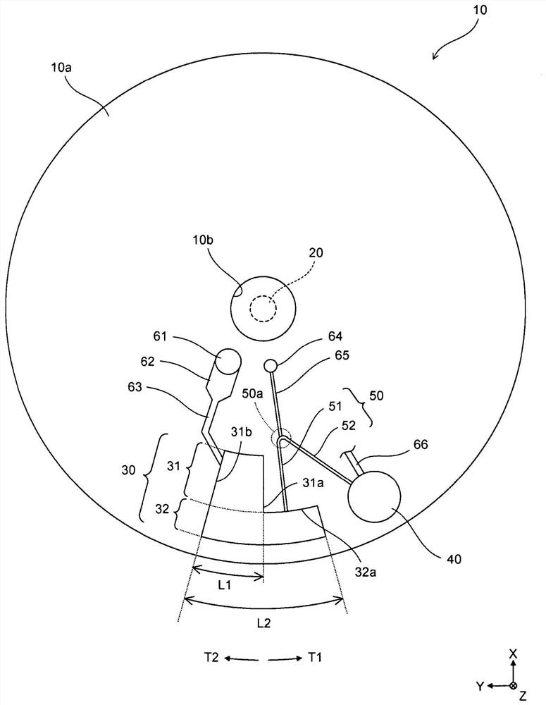
[0070] Such as figure 1 As shown, the measurement cartridge 10 is a measurement cartridge for separating the liquid component from the sample by centrifugation and measuring the liquid component. The measurement cartridge 10 is an exchangeable member that has a function necessary for separating and accumulating liquid components from a sample by centrifugation. The measurement cartridge 10 is mounted to the measurement device so as to be rotatable about a rotating shaft 20 included in the measurement device, and is configured to be able to separate a sample accommodated therein into a solid component and a liquid component by centrifugal force. The measuring device rotates the rotating shaft 20 so that the assembled measurement cartridge 10 rotates around the rotating shaft 20 .

[0071] In Embodiment 1, the sample is a blood sample of whole blood collected from a subject. The liquid component is a plasma component contained in a blood sample of whole blood. The solid comp...

Embodiment approach 2

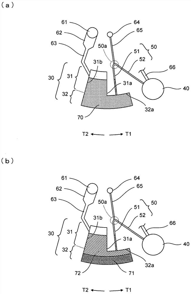
[0095] Such as Figure 5 As shown in (a), in Embodiment 2, with figure 1 Compared with the configuration of the first embodiment shown, the separation chamber 30 further includes a protruding portion 30 a protruding in the T2 direction from the radially outer inner wall portion of the inner wall portion on the T2 direction side of the second reservoir 32 . In other words, the second storage unit 32 according to Embodiment 2 includes a first region 81 and a second region 82 arranged on the rotation axis 20 side with respect to the first region 81 . The width L2 of the second region 82 in the rotational direction is smaller than the width L3 of the first region 81 in the rotational direction. The second region 82 is arranged at a position offset in the T1 direction with respect to the first region 81 . The first region 81 includes an inner wall 81a extending along the rotation direction in plan view. The inner wall 81 a is located on the T2 direction side of the first region...

Embodiment approach 3

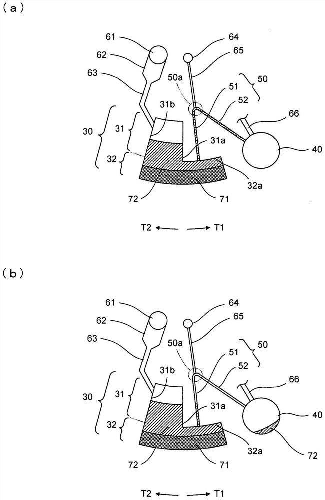
[0101] Such as Figure 6 As shown in (a), in Embodiment 3, with Figure 5 Compared with the configuration of Embodiment 2 shown in (a), the separation chamber 30 further includes a protruding portion 30b protruding in the T1 direction from the radially outer inner wall portion of the inner wall of the second reservoir 32 on the T1 direction side. In other words, compared with the second embodiment, the first region 81 of the third embodiment has a shape extending in the T1 direction. The first region 81 further includes an inner wall 81b extending along the rotation direction in plan view. The inner wall 81 b is located on the T1 direction side and radially inward of the first region 81 , and is connected to the second region 82 .

[0102] In the third embodiment, the width L3 of the first region 81 is longer than the width L3 of the second embodiment. Accordingly, during centrifugation, the solid content 71 can be accommodated more efficiently in the first region 81 . In ...


PUM


Abstract

The present invention provides a cartridge for measurement and a liquid feeding method capable of suppressing contamination of blood cell components when transferring plasma components separated by centrifugation and improving the measurement accuracy of plasma components. The cartridge for measurement includes a separation chamber including a first storage part and a second storage part, and the second storage part is opposed to the first storage part is arranged in a direction away from the rotation shaft, and has a larger width in the rotation direction around the rotation shaft than the first storage part; The inner wall of one side is connected. The flow path includes a flow path for moving the blood sample introduced from the sample introduction port to the separation chamber, and a flow path for moving the plasma component separated in the separation chamber by the capillary phenomenon.

Description

technical field [0001] The present invention relates to a measurement cartridge and a liquid feeding method for separating a liquid component from a sample by centrifugation for measurement. Background technique [0002] Patent Document 1 discloses a configuration in which a sample is analyzed using a disc-shaped bioanalysis device. [0003] Specifically, as Figure 20 As shown in (a), the blood 402 injected into the blood storage unit 401 is transferred to the blood separation unit 404 through the blood flow channel 403 by the centrifugal force generated by the rotation of the bioanalysis device 400 . The inside of the blood separation unit 404 is divided into a plasma storage unit 406 and a blood cell storage unit 407 by a blood separation wall 405 . In addition, a plasma collection capillary 408 and a ventilation flow path 409 are formed on the blood separation wall 405 so as to connect the plasma storage part 406 and the blood cell storage part 407 . Such as Figure 20...

Claims


Application Information

Patent Timeline
Patent Type & Authority Patents(China)
IPC IPC(8): G01N33/48B04B1/00B04B11/04
CPCB04B1/00B04B11/04G01N33/48B04B2011/046B01L3/502753B01L2300/0803B01L2300/087B01L2400/0688B01L2300/0864B01L2400/0406B01L2400/0409G01N33/491B01D21/26B01L3/502B01L2300/0848
Inventor 能势智之堀井和由友田小百合
Owner SYSMEX CORP
Why Eureka
Try Eureka