Multi-level progressive classification and identification method for small-current ground faults

A technology of small current grounding and classification identification, which is applied in the direction of fault location, measurement of electricity, and measurement of electrical variables, etc., can solve the problems of single and fuzzy identification types, achieve clear structure, promote continuous improvement, and be easy to program.

Active Publication Date: 2018-05-08
STATE GRID HUBEI ELECTRIC POWER RES INST +2
7 Cites 16 Cited by

AI-Extracted Technical Summary

Problems solved by technology

[0004] In order to overcome the problems of single and fuzzy identification types in the existing fault identification technology, the present invention proposes a multi-level progressive classification identification method for small current grounding fa...

Abstract

The invention relates to a multi-level progressive classification and identification method for small-current ground faults. Four layers of progressive fault classification data modules are arranged from top to bottom based on time domain characteristics and properties of fault points of fault characteristics, so that problems of incomplete small-current ground fault classification and single identification type and the like are solved. The method comprises is implemented by five steps; fault waveform characteristics of a zero-sequence voltage and a zero-sequence current are extracted at different layers; layer-by-layer fault type identification is carried out by using time domain characteristic identification, a heuristic segmentation algorithm, and an FFT analysis and the like; and thena fault type representing the fault characteristics comprehensively is obtained. With the method provided by the invention, an unclear concept problem during the fault identification process is solved; on the one hand, a fault factor and a distribution rule are obtained deeply and the refined level of the operation and checking management of the distribution network is perfected continuously; andon the other hand, the operation and maintenance personnel is assisted in finding out a potential safety hazard of the distribution network timely, so that the fault searching time is shortened and the operation reliability of distribution network is improved continuously.

Application Domain

Technology Topic

Image

  • Multi-level progressive classification and identification method for small-current ground faults
  • Multi-level progressive classification and identification method for small-current ground faults
  • Multi-level progressive classification and identification method for small-current ground faults

Examples

  • Experimental program(1)

Example Embodiment

[0055] In order to achieve the above purpose, the technical solutions adopted in the present invention are as follows: figure 1 , 2 :
[0056] The fault characteristics are decomposed into 4 different factors, and analyzed at different levels to form a multi-level progressive fault classification and identification method, which provides a basis for further establishment of a fault identification model.
[0057] The method for multi-level progressive classification and identification of low-current grounding faults includes setting up a four-layer progressive fault classification data module according to the characteristics of low-current grounding faults, so as to provide a basis for further establishing a fault identification model.
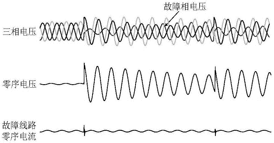
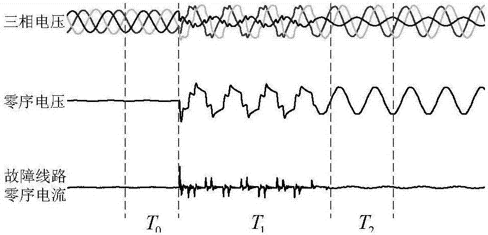
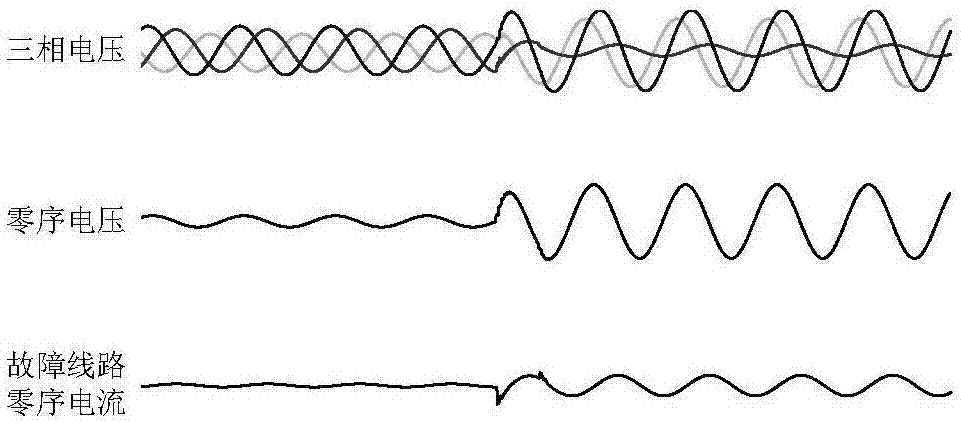
 Specifically, it includes the first step. Module layer 1, the first module layer 1 divides faults into permanent faults, transient faults and intermittent faults according to the time-domain characteristics of the faults. Permanent faults refer to the grounding state in which the fault persists after single-phase grounding until manual processing; Transient fault refers to the grounding state in which the fault disappears after a period of time and the system automatically returns to normal; Module layer 2 divides faults into single faults and developing faults according to the complexity of the faults. Single faults refer to the grounding state in which the nature of the fault remains unchanged during the fault process, and developing faults refer to the grounding state in which the nature of the fault changes during the fault process. The third module layer 3, the third module layer 3 divides the faults into linear faults and nonlinear faults according to the nature of the grounding point. The grounding point has an arcing state; the fourth module layer 4, the fourth module layer 4 divides linear faults into metallic faults, low-resistance faults and high-resistance faults according to the size of the transition resistance; divides nonlinear faults into arc light High-resistance faults refer to linear faults with transition resistance greater than 1kΩ, low-resistance faults refer to linear faults with transition resistance less than 1kΩ, and metallic faults refer to linear faults with transition resistance of 0 or close to 0 , arc high-resistance fault refers to the nonlinear fault with the minimum value of the transition resistance greater than 1kΩ, and arc-type low-resistance fault refers to the nonlinear fault with the minimum value of the transition resistance less than 1kΩ;
[0058] According to the above-mentioned progressive fault classification data module structure, according to the following multi-level progressive identification method of small current grounding fault type, extract the features of different levels in the fault waveform to identify the fault, which specifically includes the following steps:
[0059] Step 1: Collect the zero-sequence voltage of the bus and the zero-sequence current signal of each outlet;
[0060] Step 2: Identify permanent faults, transient faults and intermittent faults in combination with manual processing and zero-sequence voltage attenuation;
[0061] The specific process of step 2 is:
[0062] a. Detect the amplitude of the zero-sequence voltage per cycle, and calculate the attenuation degree α of the zero-sequence voltage waveform per cycle from left to right T; Set the attenuation degree α of the zero-sequence voltage of the T-th cycle T is the ratio of the zero-sequence voltage amplitude of the T-th cycle to the zero-sequence voltage amplitude of the T-1th cycle, namely:
[0063]
[0064] b. Define the counter M 1 , M 2 To identify the progress and completion of the recovery process of the system.
[0065] counter M 1 The initial value is 0, when U 0U op.set And when α<0.85, the counter M is every other cycle 1 add 1, otherwise M 1 clear, where U 0 zero-sequence voltage amplitude, U op.set is the starting value of the zero-sequence voltage of the protection device, and α is the attenuation degree; then when M 12, it is considered that the system is in the recovery process;
[0066] counter M 2 The initial value is 0, when U 0 cl.set , every other cycle counter M 2 add 1, otherwise M 2 clear, where U cl.set It is the return value of the zero-sequence voltage of the protection device. then when M 22, it is considered that the system recovery process has been completed;
[0067] c. Define the flag value F, the initial value is 0, if the fault is handled manually, the value is 1, otherwise it remains unchanged.
[0068] If F=0 in the process, and α<1, the final M 22, judge that the fault is a transient fault;
[0069] If F=0 in the process, there is M 12 and α>1, the final M 22, judge the fault as an intermittent fault;
[0070] If F=0 in the process, and M 2 <2, the final F=1, the fault is judged to be a permanent fault.
[0071] Step 3: Use the heuristic segmentation algorithm (BG algorithm) to process the zero-sequence current, identify single faults and developmental faults, and perform segmentation processing on the fault waveform;
[0072] The specific process of step 3 is:
[0073] a. Calculate the number of points N of the left and right parts of the sequence at any point i in the sampling sequence X(t) l , N r , the mean μ l (i), μ r (i) and standard deviation s l (i), s r (i), then the combined deviation s of the sequences on both sides of point i can be obtained D (i) is:
[0074]
[0075] b. Calculate the t-hypothesis test statistic T(i) of the significant difference between the means on the left and right sides of point i as:
[0076]
[0077] And repeat the above calculation process for each point in X(t) from left to right to obtain the test statistic value sequence T(t);
[0078] c. Calculate the maximum value T in T(t) max Statistically significant P max , P max Generally it can be expressed as:
[0079]
[0080] formula, is an incomplete beta function, is the upper limit of the integral of the incomplete beta function, δv and δ are the two parameters of the incomplete beta function, and v is the degree of freedom of the t-test. Among them, according to Monte Carlo simulation, γ=4.19lnN-11.54, δ=0.40, ν=N-2, and N is the total number of sampling sequence points.
[0081] d. Set the threshold value P 0 =0.95, when the maximum value T in T(t) max Statistically significant P maxP 0 , it means that the mutation of X(t) is significant, and the corresponding wave recording data has a trend mutation, that is, the fault is a developmental fault, where T max The corresponding point i is the mutation point, and the waveform is divided into two parts from point i.
[0082] Step 4: Perform FFT analysis on the zero-sequence current, and identify linear and nonlinear faults by comparing the amplitude-frequency characteristics of the zero-sequence current before and after the fault;
[0083] The specific process of step 4 is:
[0084]a. Perform FFT analysis on the zero-sequence current waveform obtained in step 3;
[0085] b. Take the cycle before the fault as the reference quantity T 0 , each cycle after the fault is T 1 , T 2 …T n , calculate T i (i=1,2,...,n) The percentage of each frequency amplitude relative to the fundamental frequency;
[0086] c. Calculate T i relative to T 0 The percentage change of the amplitude of each frequency, and sort the frequency points from large to small to obtain T i The average value of the percentage change in amplitude of the first 5 frequency points μ i;
[0087] d. Define the initial value of the counter N as 0, when μ i When <10%, N is incremented by 1; otherwise, N is cleared;
[0088] e. When M 1 When <2, the system is not in the recovery process; if N>2 exists at the same time, it is considered that the high-frequency component of the waveform does not change significantly, and the fault is judged as a linear fault, otherwise it is a nonlinear fault;
[0089] In the step 4, using the feature of complete classification in the multi-level classification method of low-current grounding faults, firstly, the identification of linear faults is performed to ensure that the instantaneous nonlinear grounding arc is not ignored.
[0090] Step 5: Identify high-resistance faults and low-resistance faults by the magnitude of the zero-sequence voltage;
[0091] The specific process of step 5 is:
[0092] a. According to the pre-fault phase voltage U m and the zero-sequence current 3I of the fault line at the time of metallic fault 0 , calculate the system zero-sequence impedance Z S0 :
[0093]
[0094] b. Judge the size of the transition resistance according to the zero-sequence voltage at the bus:
[0095]
[0096] Step 6: Combine the identification results of different levels to obtain the final fault type;
[0097] The method of the present invention will be described in further detail below with reference to the accompanying drawings and the recorded wave data of several typical fault types.
[0098] by image 3 Taking the intermittent ground fault shown as an example, the attenuation degree threshold α described in step 2 of the fault identification process set Be explained:
[0099] The voltage level of the distribution network is low, and the grounding point is unstable. After the fault disappears, the system has a three-phase voltage recovery process. Especially in the resonant grounding system, due to the function of the arc suppression coil, the voltage recovery may require dozens of power frequency cycles. . Therefore, the recovery process of the system can be identified through the decay process of the zero-sequence voltage, and intermittent faults can be identified by judging whether the fault occurs again during the system recovery process. During the recovery process, the zero sequence voltage u 0 is the decay component of free oscillation, which can be expressed as
[0100]
[0101] In the formula, u 0 is the zero-sequence voltage during the recovery process; U pm is the amplitude of the phase voltage; α is the attenuation coefficient, which is related to the damping rate of the power grid; e is a natural constant; ω 0 is the free oscillation angular frequency; is the initial phase angle of the voltage and current for the system recovery process. Therefore, the zero-sequence voltage amplitude decays to the original 1/e per cycle 2πα. It is considered that the longest duration of the system recovery process is 20 power frequency cycles, and when the attenuation is below 5% of the fault amplitude, the system is considered to be back to normal, and each cycle at least decays to 85% of the previous cycle. Therefore, when α<0.85, the system is considered to be in the recovery process.
[0102] by Figure 4 , Figure 5 Taking the two different types of developing ground faults shown as examples, the BG algorithm described in step 3 is described:
[0103] The zero-sequence currents of two different types of faults are processed by the BG algorithm respectively, and the test statistic value sequence T(t) is obtained as follows: Image 6 , Figure 7 As shown in the figure, it can be seen that the T-test sequence at the mutation point all achieves the maximum value, which proves that the BG algorithm can effectively identify the trend change in the fault signal.
[0104] by Figure 4 As an example, the FFT analysis described in step 4 is described:
[0105] Figure 4 The fault oscillogram shown has three stages: pre-fault, nonlinear fault, and linear fault, corresponding to T 0 , T 1 , T 2. FFT analysis is performed on them respectively, and the amplitude-frequency characteristics are as follows Figure 8 As shown, it can be calculated that T 1 , T 2 relative to T 0 The average value of the percent change in amplitude is μ 10 =95.72%, μ 20 = 9.663%. It can be seen that detecting the change of the frequency component of the zero-sequence current can effectively identify linear faults and nonlinear faults.
[0106] The transition resistance measurement described in step 5 is related to the capacitance current of the system, and its accuracy cannot be verified by on-site data. Select 170 groups of on-site fault recording waves to test the fault identification method described in steps 2-4 of the present invention, and the test results are shown in Table 1. Show:
[0107] Table 1 Test results of the identification method of small current ground fault types
[0108]
[0109] The comprehensive test accuracy rate is over 92%, which proves that the fault identification method described in steps 2-4 is effective.
[0110] The validity of the high-resistance fault identification method described in step 5 is tested by artificial grounding test, and the test data records are shown in Table 1:
[0111] Table 1 Artificial grounding test data
[0112]
[0113]
[0114] The zero-sequence voltage values ​​measured in the test are all smaller than the theoretical calculation values. The possible reason is that it is difficult to achieve complete metallic grounding when artificially grounded, the fault phase voltage is not 0, the measured capacitance current is small, and the system is zero. The calculated value of sequence impedance is too large, and the final zero-sequence voltage is too large. Within the allowable error range, it can be considered that the test results under the two grounding methods are consistent with the theoretical calculation results, which proves that the zero-sequence voltage high-resistance identification method described in step 5 is effective.
[0115] The above-mentioned embodiments only represent several embodiments of the present invention, and the descriptions thereof are specific and detailed, but should not be construed as a limitation on the scope of the patent of the present invention. It should be pointed out that for those of ordinary skill in the art, without departing from the concept of the present invention, several modifications and improvements can also be made, which all belong to the protection scope of the present invention. Therefore, the protection scope of the patent of the present invention should be subject to the appended claims.

PUM

no PUM

Description & Claims & Application Information

We can also present the details of the Description, Claims and Application information to help users get a comprehensive understanding of the technical details of the patent, such as background art, summary of invention, brief description of drawings, description of embodiments, and other original content. On the other hand, users can also determine the specific scope of protection of the technology through the list of claims; as well as understand the changes in the life cycle of the technology with the presentation of the patent timeline. Login to view more.

Similar technology patents

Fluorine-cation-containing WPU (waterborne polyurethane) and preparation method thereof

ActiveCN103044649AClear structureRaw material controllableSolventIsocyanate compound
Owner:无锡智慧兴宜信息技术有限公司

Classification and recommendation of technical efficacy words

Why Eureka
Try Eureka