Eureka AIR delivers breakthrough ideas for toughest innovation challenges, trusted by R&D personnel around the world.

Reinforcer mounting machine

A technology of pasting reinforcement and socket, which is applied in the direction of electrical components, laminated printed circuit boards, printed circuit manufacturing, etc. It can solve the problems of low bonding efficiency of bonding and reinforcing machines, slow bonding efficiency of manual bonding, and inability to complete one-time processing, etc. , to achieve the effect of improving heating and reinforcing efficiency, saving manpower, and saving labor costs

Pending Publication Date: 2018-05-11
NETRON SOFT-TECH ZHUHAI CO LTD
View PDF0 Cites 0 Cited by
  • Summary
  • Abstract
  • Description
  • Claims
  • Application Information

AI Technical Summary

Problems solved by technology

[0005] 1. The efficiency of manual lamination is slow and the lamination accuracy is low. The tolerance of conventional manual lamination is ±0.15mm, the highest can be ±0.1mm, and the labor cost is high;
[0006] 2. There are few kinds of materials supplied by the existing sticking and reinforcing machines, usually only 2 types of materials can be supplied, that is, if the FPC needs to paste more than 3 types of reinforcing plates on the same side, it cannot be processed at one time, and it needs to be divided into two or more times Fitting can be completed;
[0007] 3. The bonding efficiency of the existing patching and reinforcing machine is low, because there are relatively few placement heads, and each placement head can only absorb one reinforcement for each suction, and most of the time is wasted in sucking materials back and forth on the path, so the bonding efficiency is 1800 points / hour

Method used


Image

  • Reinforcer mounting machine
  • Reinforcer mounting machine
  • Reinforcer mounting machine

Examples


Embodiment Construction

[0033] The following will clearly and completely describe the technical solutions in the embodiments of the present invention with reference to the accompanying drawings in the embodiments of the present invention. Obviously, the described embodiments are only some, not all, embodiments of the present invention. Based on the embodiments of the present invention, all other embodiments obtained by persons of ordinary skill in the art without making creative efforts belong to the protection scope of the present invention.

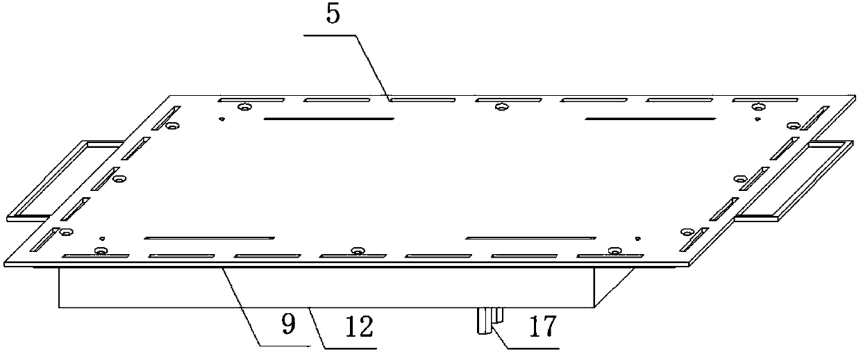
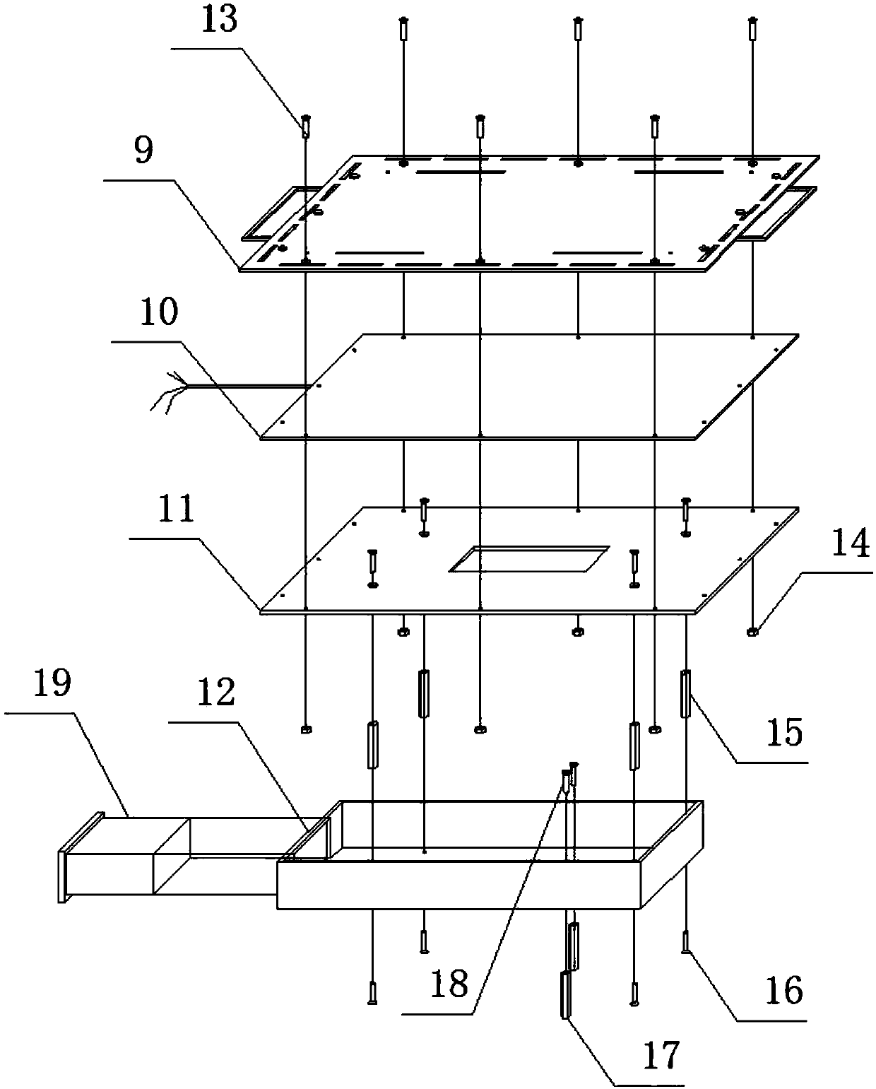
[0034] The present invention provides such figure 1 A pasting and strengthening machine shown includes a waiting area 1, a processing area 2 and a plate output area 3, and is characterized in that: the processing area 2 is set on the side of the waiting area 1, and the plate output area 3 is set on the On one side of the processing area 2, the bottom end of the waiting area 1 is provided with a transmission track 4, which is conducive to providing transmission...


PUM


Abstract

The invention discloses a reinforcer mounting machine, which comprises a material waiting area, a processing area and a plate output area. The processing area is arranged at one side of the material waiting area; and the plate output area is arranged at one side of the processing area. The bottom end of the material waiting area is provided with a transmission track. One end of the transmission track extends to one side of the bottom end of the plate output area; the top portion of the transmission track is provided with a heating platform; and the heating platform is in transmission connection with the transmission track. One side of the bottom end of the transmission track is provided with a through-type socket, and the through-type socket is arranged at the bottom portion of the material waiting area; and an elastic socket is arranged at the bottom portion of the processing area. The reinforcer mounting machine, by utilizing mounting efficiency, precision and mounting action of a YAMAHA surface-mounting machine itself, can effectively improve work efficiency, and can reduce mounting errors, thereby preventing waste of marginal materials, saving a lot of manpower and labor cost,and reducing waste of resources and processing cost; and the produced FPC is high in quality, and production efficiency and production quality can be greatly improved.

Description

technical field [0001] The invention relates to the field of FPC board pasting and reinforcing devices, in particular to a pasting and reinforcing machine. Background technique [0002] With the extensive use of electronic products, the integration of FPC boards as flexible circuits has been widely used in various electronic products. In the process of strengthening the board, various reinforcing boards are attached to the FPC board to enhance the supporting capacity of the FPC board. [0003] There are manual lamination and equipment lamination for lamination of reinforcement boards. Manual lamination requires relatively high proficiency of employees, low lamination efficiency and low precision, and has been gradually replaced by equipment now; equipment lamination has low requirements for employees , High bonding efficiency and high precision, so using equipment instead of manual production is the first choice of most manufacturers. [0004] Existing pasting and reinforc...

Claims


Application Information

Patent Timeline
IPC IPC(8): H05K3/00
CPCH05K3/0058H05K2203/1105
Inventor 刘惠民彭勇强
Owner NETRON SOFT-TECH ZHUHAI CO LTD
Why Eureka
Eureka Blog
Learn More