Fusion welding auxiliary heating friction-stir welding method under prefabricated groove situation

A technology of friction stir and welding method, which is applied in the field of fusion welding auxiliary heat stir friction welding, which can solve the problems of joint welding defects, performance degradation, microstructure and mechanical properties difference, etc., and achieve the effect of improving joint performance and welding operation is simple

Inactive Publication Date: 2018-11-23
GUILIN UNIVERSITY OF TECHNOLOGY
View PDF4 Cites 4 Cited by
  • Summary
  • Abstract
  • Description
  • Claims
  • Application Information

AI Technical Summary

Problems solved by technology

However, these auxiliary heat sources are used to heat the upper surface of the workpiece to be welded, and the bottom of the workpiece to be welded has not been effectively preheated. There is a huge difference in the microstructure and mechanical properties of the joints, and the joints are prone to welding defects, and the performance will also decrease accordingly.

Method used


Image

  • Fusion welding auxiliary heating friction-stir welding method under prefabricated groove situation

Examples


Embodiment 1

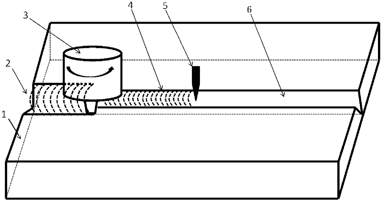
[0012] Such as figure 1 As shown, the workpiece 1 to be welded is low-carbon micro-alloy steel with a thickness of 7mm. Before welding, a V-shaped groove 6 is prefabricated on the workpiece 1 to be welded. The width and height of the V-shaped groove 6 are 6mm and 6mm respectively. The welding process Firstly, use mixed gas (65% Ar + 26.5% He + 8% CO 2 + 0.5% O2) shielded welding to weld the workpiece 1 to be welded, so that the molten welding wire fills the V-shaped groove 6, and the welding During the process, the voltage is 25V, the current is 200A, the welding speed is 75mm / min, and the diameter of the welding wire is 1.2mm. During the welding process, the friction stir welding follows the mixed gas shielded welding, the stirring head 3 is located 30mm behind the mixed gas shielded welding torch 5, and the friction stir welding travel speed is 75mm / min, which is consistent with the melting welding speed; the material of the stir head 3 It is W-Re alloy, the diameter of the...

Embodiment 2

[0014] The workpiece 1 to be welded is a 30mm thick 7050 aluminum alloy thick plate. Before welding, a V-shaped groove 6 is prefabricated on the workpiece 1 to be welded. The width and height of the V-shaped groove 6 are 20mm and 27mm respectively. MIG welding completes the welding of the workpiece, so that the molten welding wire fills the V-shaped groove 6. During the welding process, the voltage is 23V, the current is 240A, the welding speed is 50mm / min, and the diameter of the welding wire is 1.2mm. During the welding process, the friction stir welding follows the MIG, the stirring head 3 is located 45mm behind the fusion welding torch 5, and the friction stir welding travel speed is 50mm / min, which is consistent with the fusion welding travel speed. The material of the stirring head 3 is tool steel, the diameter of the shoulder of the stirring head 3 is 40mm, the stirring needle is tapered, the needle length is 28mm, and the rotational speed during the friction stir weldin...

Embodiment 3

[0016] The workpiece 1 to be welded is a 10mm thick red copper plate. Before welding, the unilateral V-shaped groove 6 is prefabricated on the workpiece 1 to be welded. The width and height of the unilateral V-shaped groove 6 are 5mm and 7mm respectively. During the welding process, first Use MIG welding to complete the welding of the workpiece, so that the molten welding wire fills the V-shaped groove 6. During the welding process, the voltage is 31V, the current is 240A, the welding speed is 50mm / min, and the diameter of the welding wire is 1.2mm. During the welding process, friction stir welding followed closely, the stirring head 3 was 30 mm behind the fusion welding torch 5, and the friction stir welding traveling speed was 50 mm / min, which was consistent with the fusion welding traveling speed. The material of the stirring head 3 is high-speed steel, the diameter of the shoulder of the stirring head 3 is 20mm, the stirring needle is tapered, the length of the needle is 9....


PUM

PropertyMeasurementUnit
diameteraaaaaaaaaa

Abstract

The invention discloses a fusion welding auxiliary heating friction-stir welding method under a prefabricated groove situation. The method comprises the steps of firstly prefabricating grooves (6) with different shapes on a workpiece (1) to be welded, then utilizing fusion welding for accomplishing the welding of the workpiece (1) to be welded, and filling molten liquid metal in the grooves (6) for preheating welded joints, wherein during the welding process, friction-stir welding follows fusion welding, a stirring head (3) is located at the position which is 0 to 300mm away from a fusion welding gun (5), and the welding speed of the friction-stir welding and the welding speed of the fusion welding stay the same during the welding process, so that the distance between the stirring head (3)and the fusion welding gun (5) stays the same. The fusion welding energy is uniform, the workpiece to be welded is effectively preheated, the follow-up friction-stir welding plays a role in improvingthe connector performance, and through the combination of two welding modes, the weaknesses can be greatly avoided, and the welding operation is carried out simply, conveniently and flexibly.

Description

technical field [0001] The invention relates to the field of welding technology, in particular to a method of fusion welding auxiliary heat stir friction welding in the case of prefabricated grooves. Background technique [0002] Friction stir welding is a solid-state welding technology that can avoid defects such as pores, thermal cracks, and segregation in welded joints caused by the solidification of the molten pool. In addition, the friction stir welded joint metal undergoes strong recrystallization, so the grains are fine and the properties are excellent. In the friction stir welding process, the heat source mainly comes from the frictional heat and plastic deformation heat between the stirring head and the workpiece. The heat production is low, the workpiece temperature is low, and the material deformation resistance is high. Therefore, when welding high-melting point metals or thick plates, the stirring head will bear a huge torque and friction, and the stirring head...

Claims


Application Information

Patent Timeline
Patent Type & Authority Applications(China)
IPC IPC(8): B23K28/02
CPCB23K28/02
Inventor 崔洪波王春霞唐鑫李存军
Owner GUILIN UNIVERSITY OF TECHNOLOGY
Why Eureka
Try Eureka