Method of preheating steelmaking ladles

a steelmaking ladle and preheating technology, applied in the field of steelmaking, can solve the problems of high variability and unpredictable length of time during which a ladle is empty, cold ladle, costly energy loss, etc., and achieve the effect of reducing the amount of fuel consumed and inhibiting damage and wear of refractories from overheating

Active Publication Date: 2012-03-27
NUCOR CORP
View PDF10 Cites 5 Cited by
  • Summary
  • Abstract
  • Description
  • Claims
  • Application Information

AI Technical Summary

Benefits of technology

[0005]As a result, preheating of ladles before charging in the melt shop has become a common practice. Particularly, ladle preheating served to reduce damage to ladles taken out of the rotational cycle for repair and maintenance and for ladles first introduced into use. In any event, preheating reduced thermal stresses in the ladle refractory, and reduced the length of steelmaking campaigns and correspondingly increased the capacity of the steelmaking plant. However, overheating of preheated ladles also occurred which resulted in costly energy losses and resulted in unwanted and expensive refractory damage.
[0007]Accordingly, there is an unmet need for a method to reduce the amount of fuel consumed during preheating of the ladle refractories for use in steelmaking, and also to preheat the refractories of the ladle to a desired temperature efficiently while inhibiting damage and wear of the refractories from overheating.
[0010](b) heating the inner refractory surfaces of the steelmaking ladle to a desired temperature by combustion through the burner of the preheater where the emissive coating of the reflective surface facilitates preheating of the steelmaking ladle;

Problems solved by technology

Moreover, if ladles are taken off line in the steelmaking cycle, they typically cool to ambient temperatures, and the replacement ladles have to be heated from ambient temperature to operating temperature.
Moreover, the length of time during which a ladle is empty is highly variable and unpredictable.
Delays due to a major ladle repair take many hours to complete and result in a cold ladle.
However, overheating of preheated ladles also occurred which resulted in costly energy losses and resulted in unwanted and expensive refractory damage.
As a result, conventional ladle preheating processes have involved consumption of large amounts of fuel, such as natural gas, and have resulted in damage to the refractories from overheating.

Method used


Image

  • Method of preheating steelmaking ladles
  • Method of preheating steelmaking ladles
  • Method of preheating steelmaking ladles

Examples


Embodiment Construction

[0024]Shown in the accompanying drawings is a detailed description of specific embodiment of the invention, with the understanding that the present disclosure is to be considered as exemplifying the principles of the general inventive concept described in the patent claims.

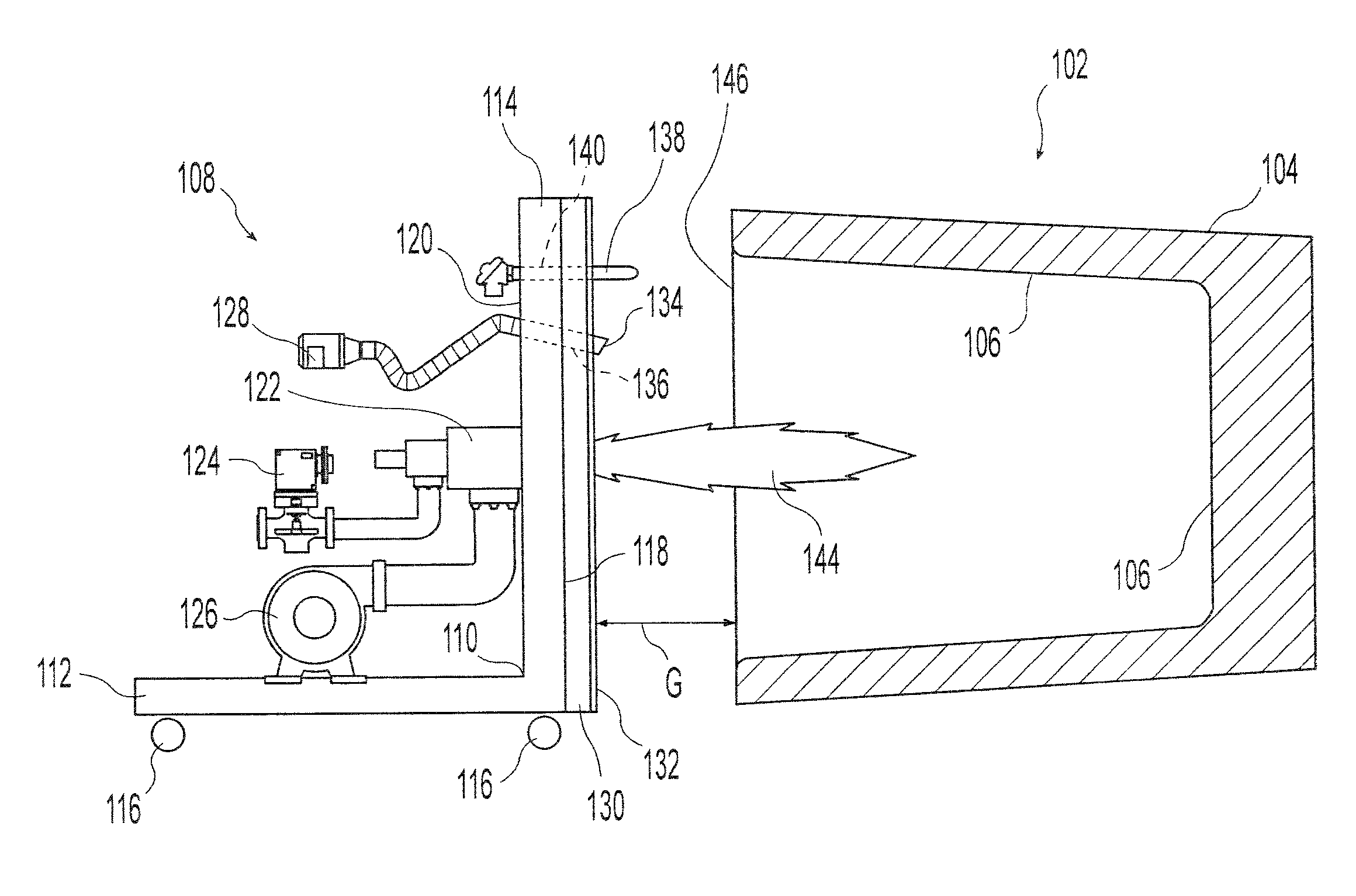
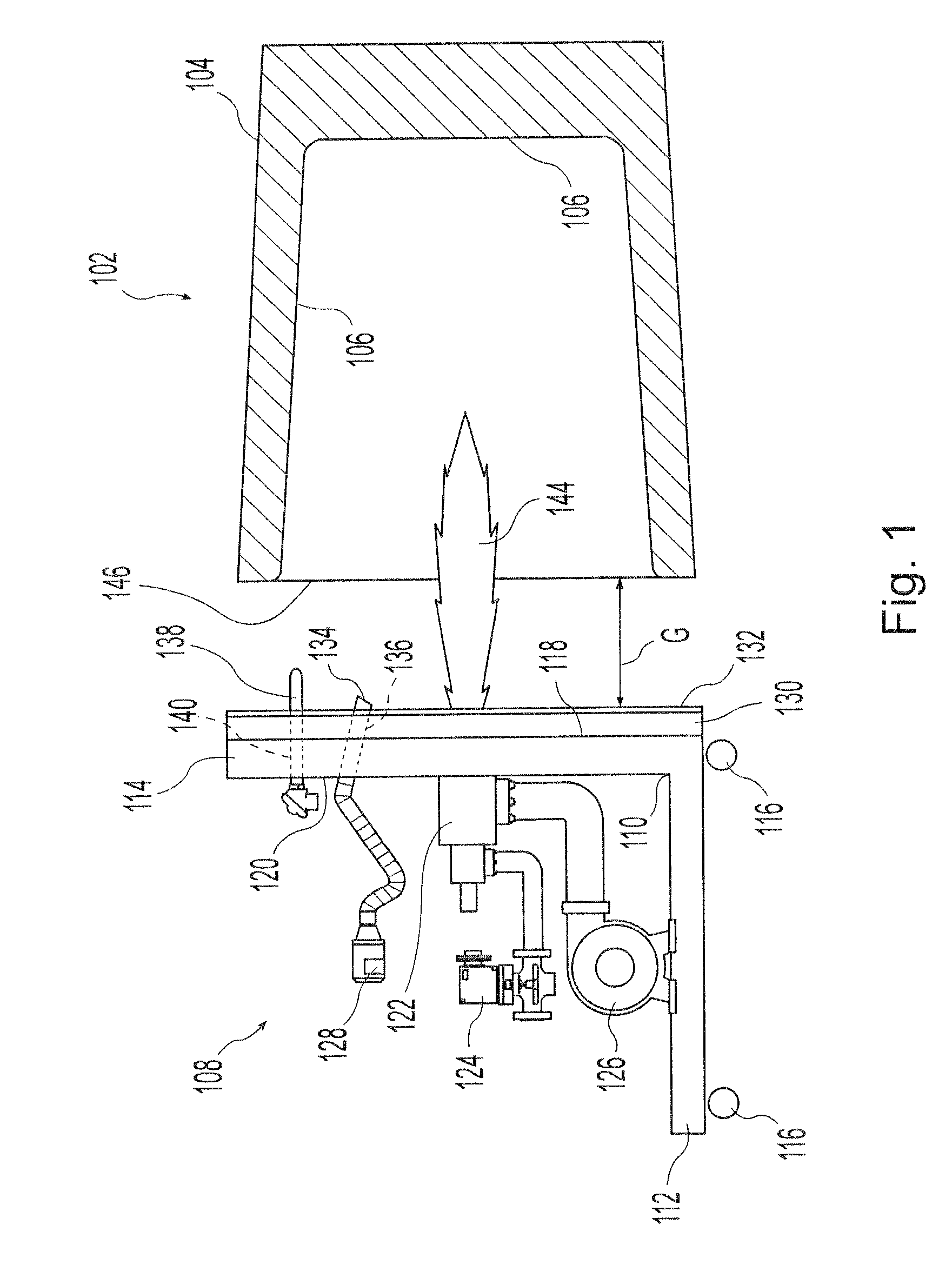
[0025]As shown in FIG. 1, a steelmaking ladle 102 (hereinafter “ladle”) for containing molten metal (e.g., molten steel) has a shell or body 104 wherein a refractory lining 106 is provided to contain molten metal during steelmaking. The refractories 106 of the ladle 102 may be refractory bricks lining an inner surface of the body 104 of the ladle 102. In an alternative embodiment, the refractories 106 of the ladle 102 are formed as a cast lining of the ladle 102.

[0026]With reference to FIGS. 1 and 2, a preheater 108 includes a frame or body 110 including a base portion 112 and a wall portion 114, where the base portion 112 and the wall portion 114 are lateral to one another. The base portion 112 of the preheater 1...


PUM

PropertyMeasurementUnit
temperatureaaaaaaaaaa
emissivityaaaaaaaaaa

Abstract

A method for when preheating a ladle for use in steelmaking where less fuel is consumed in heating the ladle efficiently accurately to a controlled temperature. A temperature of a preheating process is varied by controlling a burner of the heating unit based on measurements of refractories of the ladle taken by a pyrometer. The heating unit includes an emissive coating for reducing heat loss and efficient heating during the preheating process. The heating unit also includes valve mechanisms for accurately varying a flame size of the burner of the heating unit during an idle stage of the preheating process.

Description

CROSS-REFERENCE TO RELATED APPLICATION[0001]The present application is being filed as a U.S. non-provisional patent application claiming priority from and any other benefit of U.S. provisional patent application Ser. No. 60 / 943,146 filed on Jun. 11, 2007, the entire disclosure of which is hereby incorporated by reference.BACKGROUND AND SUMMARY OF INVENTION[0002]The invention relates generally to steelmaking and, more particularly, to a method of preheating steelmaking ladles. As noted in U.S. Pat. No. 5,981,917, in steelmaking brick or cast refractory-lined ladles are used to hold the molten steel during steelmaking from an iron source, e.g., in an electric arc furnace, and to transport the molten steel to the next stage in steel processing, such as a continuous caster. These ladles may be large enough to hold 30 to 200 tons, or more, of molten steel. Since steelmaking is typically carried out continuously, several ladles are rotated through the melt shop and casting shop simultaneo...

Claims


Application Information

Patent Timeline
Patent Type & Authority Patents(United States)
IPC IPC(8): C21C7/072C21C5/30C21C5/42F27D99/00
CPCB22D41/015F27B17/00F27D19/00F27D21/0014F27D99/0033
Inventor GALEWSKI, GREGORY S.
Owner NUCOR CORP
Why Eureka
Try Eureka