
Resin pulley

A pulley and resin technology, applied in the direction of belts/chains/gears, components with teeth, portable lifting devices, etc., can solve the problems of bearing function reduction, outer ring deformation, rotation accuracy reduction, etc., to prevent creep Effect

Inactive Publication Date: 2018-05-11
NTN CORP
View PDF8 Cites 1 Cited by
  • Summary
  • Abstract
  • Description
  • Claims
  • Application Information

AI Technical Summary

Problems solved by technology

[0009] However, in the case of preventing mutual creep between the outer ring and the pulley main body by knurling, if the groove depth of the groove-shaped recesses of the ruled knurling is shallow, it cannot play a large role in preventing creep. effect, so it is necessary to form a relatively deep groove-shaped recess
[0010] At this time, in the resin pulleys described in Patent Documents 1 and 2, locking grooves are formed on the outer diameter surface of the outer ring, and knurling is performed on the bottom surface of the locking grooves to form groove-shaped recesses and protrusions. Knurls are arranged alternately in the circumferential direction. Therefore, if the groove depth of the groove-shaped recesses becomes deeper, the machining load applied to the outer ring will increase and the outer ring will deform.
Due to this deformation, when the rolling bearing rotates, abnormal noise or chattering occurs, thereby reducing the rotation accuracy, resulting in a decrease in the function of the bearing, and there are some cases where a deep groove-shaped recess that is highly effective in preventing creep cannot be formed. bad situation

Method used


Image

  • Resin pulley
  • Resin pulley
  • Resin pulley

Examples


Embodiment Construction

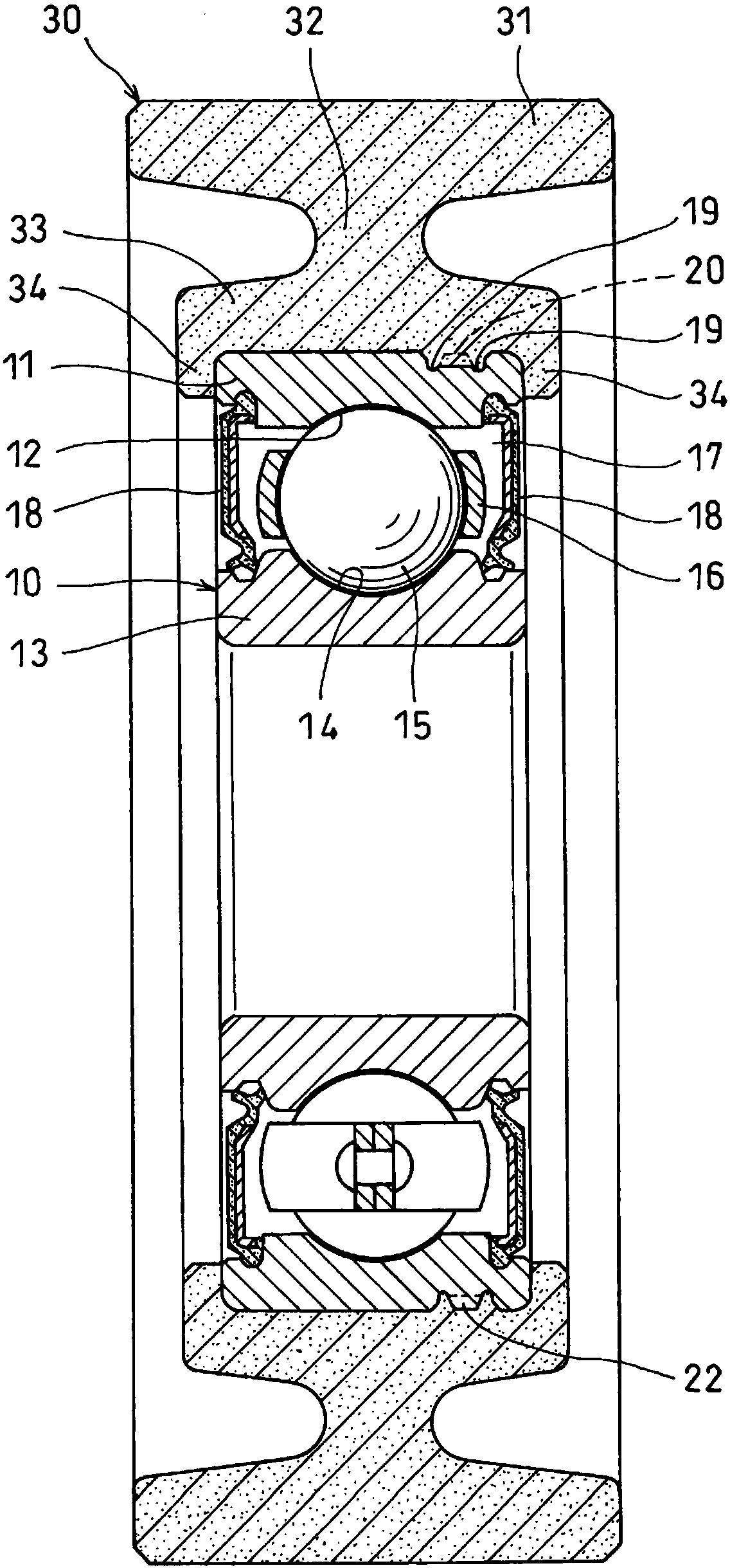
[0025] Embodiments of the present invention will be described below based on the drawings. Such as figure 1 As shown, the resin pulley is composed of a rolling bearing 10 and a pulley main body 30 provided on the outer periphery of the rolling bearing 10 .

[0026] Rolling bearing 10 is a deep groove ball bearing in which balls 15 are inserted between track grooves 12 formed on the inner diameter surface of outer ring 11 and track grooves 14 formed on the outer diameter surface of inner ring 13 , and balls 15 are held by cages 16 In this configuration, the openings at both ends of the bearing space 17 formed between the facing portions of the outer ring 11 and the inner ring 13 are closed by incorporating the seal member 18 .

[0027] In addition, the rolling bearing 10 is not limited to the deep groove ball bearing with a seal. For example, cylindrical roller bearings are also possible.

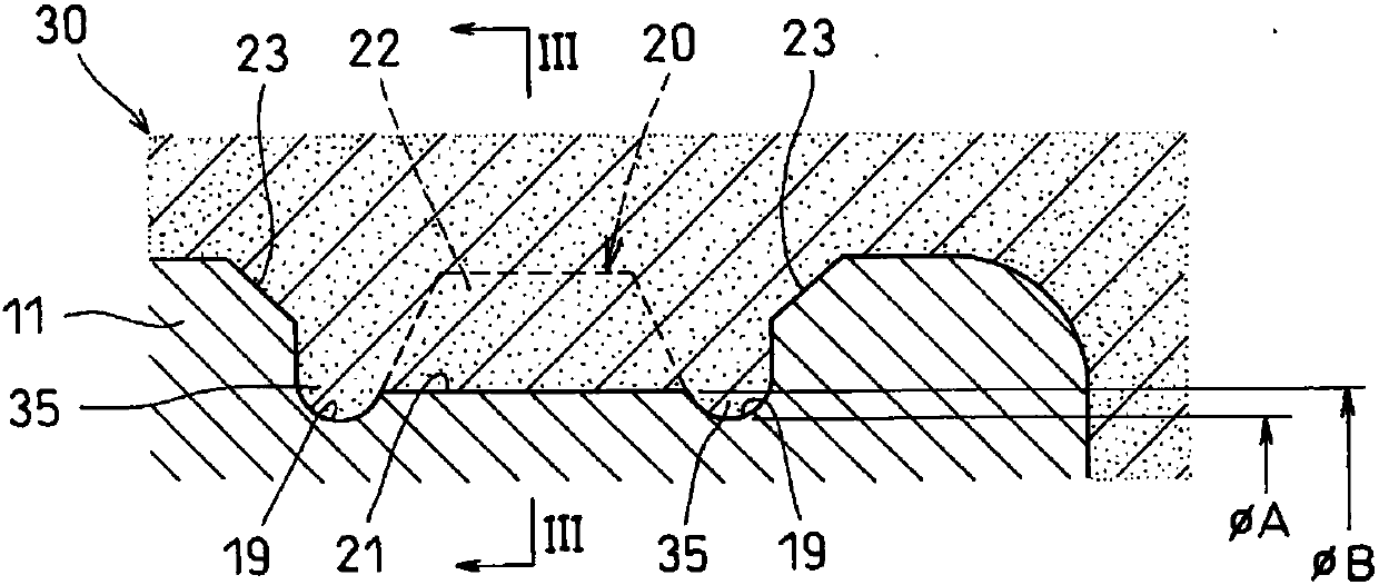
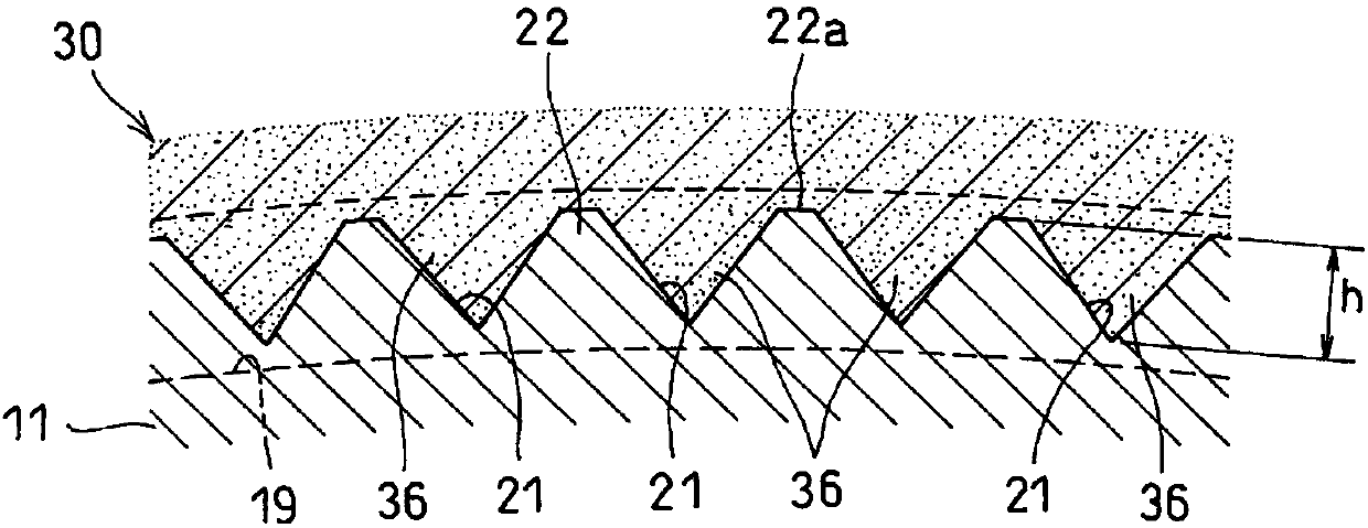
[0028] Such as Figure 2 ~ Figure 4 As shown, a pair of annular grooves 19 are provi...


PUM


Abstract

A pair of annular grooves (19) are formed in the outside-diameter surface of an outer race (11) of a rolling bearing (10) in which a pulley body (30) is molded from a resin, a linear knurl is molded by rolling in the outside-diameter surface of an annular protruding section (20) formed between the pair of annular grooves (19), and groove-shaped recesses (21) and projections (22), both of which reach the pair of annular grooves (19) at both ends, are provided alternately in the circumferential direction. The diameter ([phi]B) of a circle through the groove bottoms of the recesses (21) is greater than the diameter ([phi]A) of a circle through the groove bottom of either annular groove (19) ([phi]B > [phi]A). The pulley body (30) is molded from a resin on the outside-diameter surface of the outer race (11), and protruding parts (36), formed by filling the groove-shaped recesses (21) with a melted resin which is then solidified, are engaged with the projections (22) to prevent creeping.

Description

technical field [0001] The present invention relates to a resin pulley for guiding the movement of a timing belt of an automobile engine and a belt for driving an auxiliary machine. Background technique [0002] Idle pulleys that guide the movement of timing belts and auxiliary drive belts, and tension pulleys used to adjust belt tension are widely used in rolling bearings in terms of weight reduction and cost reduction. A resin pulley with a pulley body made of synthetic resin molded on the outer diameter surface of the outer ring. [0003] In the above-mentioned resin pulley, the material of the outer ring in the rolling bearing and the material of the pulley body have different coefficients of linear expansion, and therefore, the holding force of the outer ring of the pulley body may decrease due to the difference in the amount of thermal expansion due to temperature rise, Thereby, relative sliding (creep) occurs between the outer ring and the pulley main body. [0004]...

Claims


Application Information

Patent Timeline
Patent Type & Authority Applications(China)
IPC IPC(8): F16H55/48B29C59/02F16C19/06F16C33/58F16C35/067F16H55/36B29L31/32
CPCB29C59/02F16C35/067F16C19/06F16H55/36F16H55/48F16C33/586F16C2226/30F16C2361/63B29C59/04F16C33/581F16H55/38
Inventor 中尾吾朗
Owner NTN CORP
Learn More