Arrangement for safely removing overvoltage protection devices from the mains, independently of switchgear or backup fuses, in the event of critical operating states

An overvoltage protection and switching device technology, applied in emergency protection circuit devices for limiting overcurrent/overvoltage, emergency protection circuit devices, components of emergency protection devices, etc. leveling effect

Active Publication Date: 2018-05-11
デーンエスエープルスツェオーカーゲー
View PDF6 Cites 3 Cited by
  • Summary
  • Abstract
  • Description
  • Claims
  • Application Information

AI Technical Summary

Problems solved by technology

Since such a thermally triggered disconnection device reacts relatively slowly, it cannot promptly interrupt said faults in the range of 10 amperes up to several kiloamperes when the overvoltage protection device transitions very quickly into the low-resistance state. electric current

Method used


Image

  • Arrangement for safely removing overvoltage protection devices from the mains, independently of switchgear or backup fuses, in the event of critical operating states

Examples


Embodiment Construction

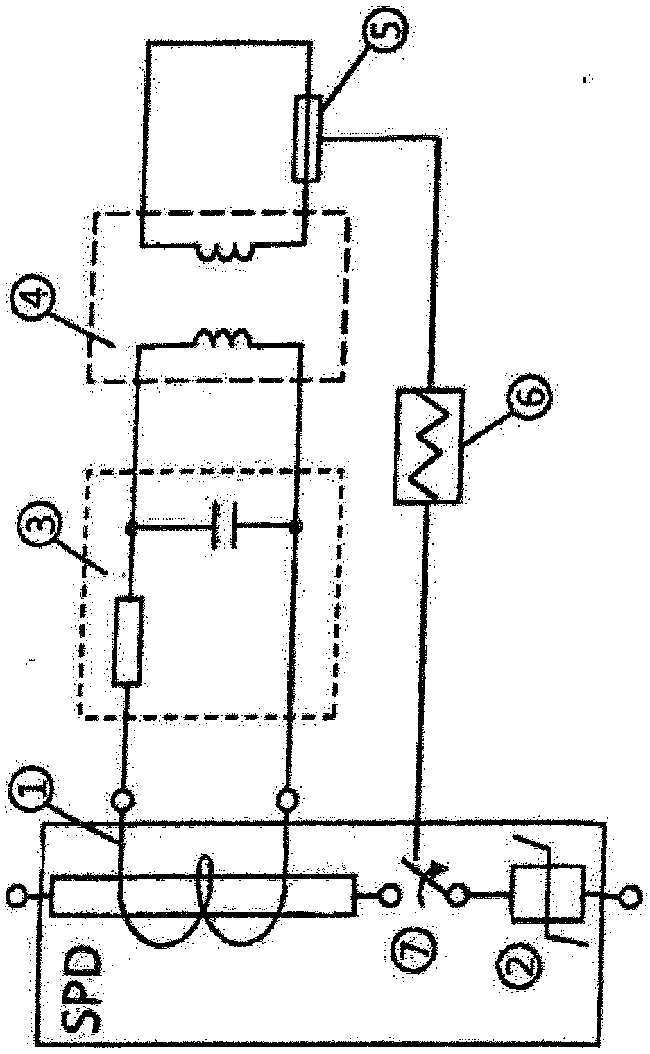
[0038] The overvoltage protection device SPD, which is preferably formed as a structural unit, comprises a toroidal core coil 1 which is arranged around the current conductor and a switching device 7 connected in series with the current conductor, which in turn is connected to a protective component, for example a metal oxide The variable resistor 2 is connected in series.

[0039] The toroidal coil 1 is connected via its terminals to the input of a low-pass circuit 3 , which is routed on the output side to a current converter transformer 4 .

[0040] A spring-pretensioned indicator fuse or fusible conductor is formed in the secondary side of the current switching transformer 4 .

[0041] The indicator safety device 5 is mechanically connected to a force booster, which is designed, for example, as a crank lever drive 6 with spring pretension. The crank lever drive acts on the switching device 7 and is able to switch the switching device 7 into the open state when the relevant...


PUM


Abstract

The invention relates to an arrangement for safely removing overvoltage protection devices from the mains, independently of switchgear or backup fuses, in the event of critical operating states, particularly transition of the overvoltage protection device to a fault or overload state, consisting of a device for sensing the current flowing through the overvoltage protection device and a switching apparatus connected in series with the overvoltage protection device. According to the invention, the device for sensing the current flowing through the overvoltage protection device is in the form ofa toroidal coil with or without a ferromagnetic core, which toroidal coil is designed such that fault currents of medium amplitude, which differ from event-dependent surge currents, are detectable. The toroidal coil is electrically connected to an indicator device or a similar means, the indicator of which is mechanically connected to the switching apparatus in order to trigger same.

Description

technical field [0001] The invention relates to a system according to claim 1 for safely disconnecting the overvoltage on the grid side independently of the switchgear or the back-up fuse in critical operating states, in particular in the event of a transition of the overvoltage protective device to a fault or overload state. An arrangement for an overvoltage protection mechanism, said arrangement comprising: means for detecting current flowing through the overvoltage protection mechanism and switching means electrically connected in series with the overvoltage protection mechanism. Background technique [0002] From EP 0 326 903 A1 a protective device against overvoltages in electrical installations is known, which has a variable resistor in a bypass branch, the leakage current is monitored by a monitoring device on the part of the variable resistor itself The non-run-related rise is monitored and the varistor is switched off if necessary. [0003] Specifically, the phase ...

Claims


Application Information

Patent Timeline
Patent Type & Authority Applications(China)
IPC IPC(8): H02H9/04H02H1/00H01H83/10
CPCH02H1/0007H02H9/042
Inventor R·布罗克P·察尔曼
Owner デーンエスエープルスツェオーカーゲー
Why Eureka
Try Eureka