
Mode division multiplexed passive optical network

A passive optical network, mode division multiplexing technology, applied in the field of passive optical network, can solve the problem of no backward compatibility, the need for coherent receivers, etc.

Inactive Publication Date: 2018-05-11
ASTON UNIV
View PDF4 Cites 9 Cited by
  • Summary
  • Abstract
  • Description
  • Claims
  • Application Information

AI Technical Summary

Problems solved by technology

However, disadvantages of this arrangement include no backwards compatibility and the need for expensive coherent receivers

Method used


Image

  • Mode division multiplexed passive optical network
  • Mode division multiplexed passive optical network
  • Mode division multiplexed passive optical network

Examples


Embodiment Construction

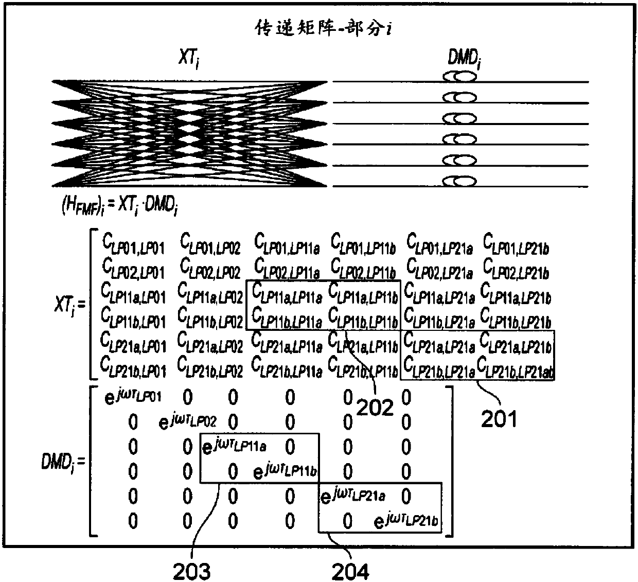
[0031] The invention is based on the recognition that in a typical FMF, the differential mode delay between degenerate modes is usually extremely low (~1 ps / km). This means XT i The matrix entries associated with these modes (eg, associated with LP11a and LP11b or LP21a and LP21b) have a low dependence on frequency. These terms are mainly responsible for introducing crosstalk as explained above. In the present invention, it is proposed to compensate the crosstalk occurring between the degenerate modes only by compensating the figure 2 The items highlighted in boxes 201, 202, 203, 204 in , to mitigate crosstalk. The compensation signal can be controlled using a one-tap optical equalizer.

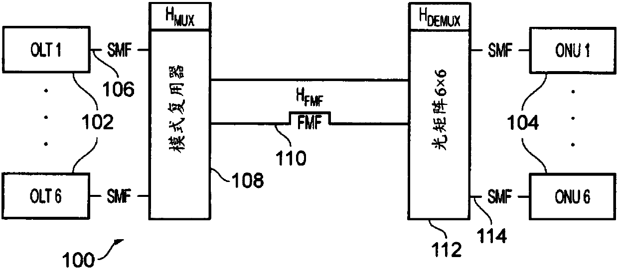
[0032] The crosstalk characteristics of the mode multiplexer 108 and the mode demultiplexer 112 shown in FIG. MUX and H DEMUX ) to describe. After inversion, these matrices can be used to fully compensate for mode mixing. However, by properly designing the mode multiplexer 108 and mode...


PUM


Abstract

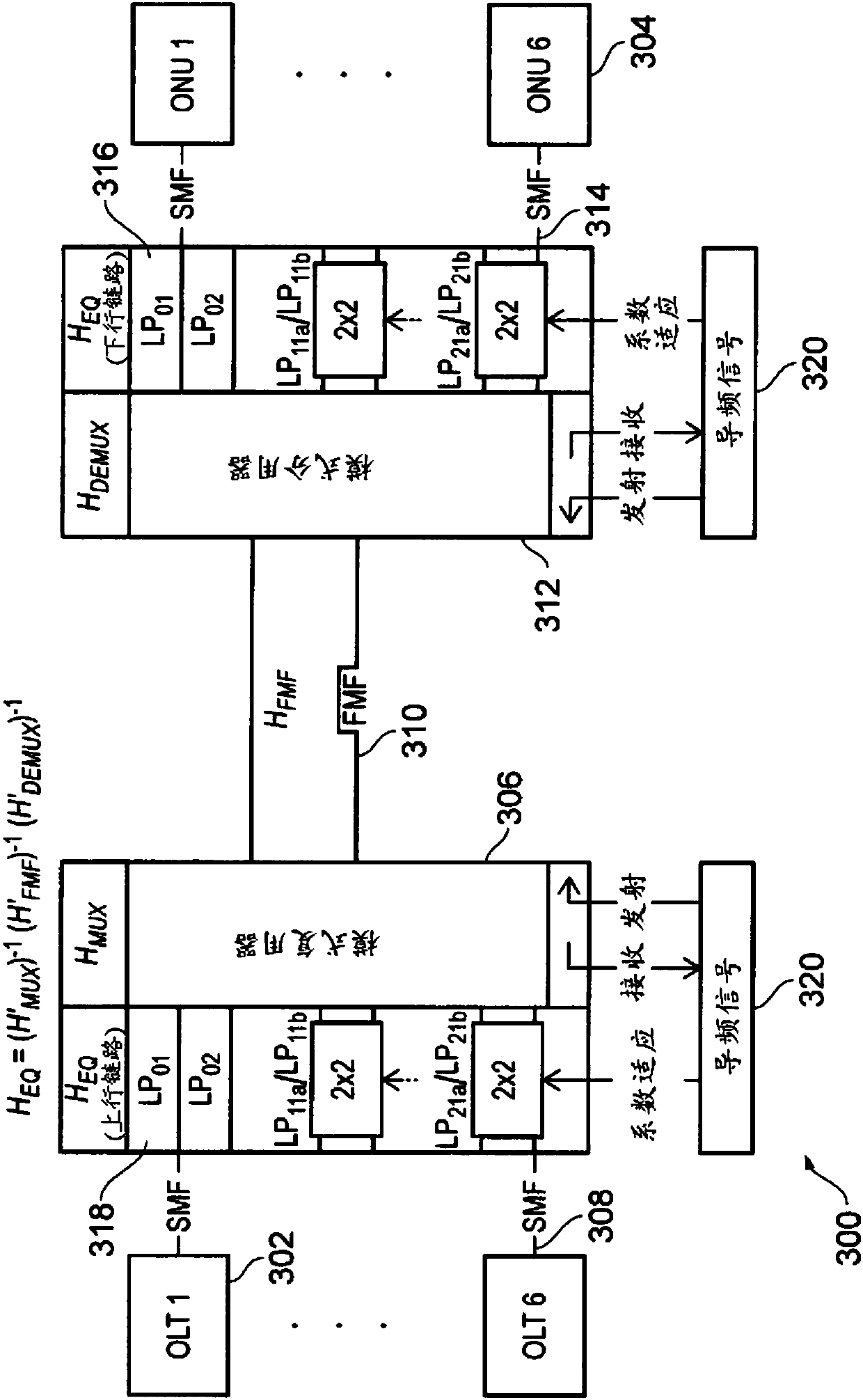
A mode division multiplexing passive optical network (PON) in which channel estimation / inversion is performed in the optical domain. The PON comprises a plurality of input channels; a multiplexer having a plurality of input ports connected to a respective one of the input channels; an optical fiber having an uplink end connected to an output port of the multiplexer, whereby the multiplexer outputsa mode multiplexed signal corresponding to the optical signals from the plurality of input channels. The PON includes an optical equalizer arranged to transfer power between optical signals having different modes to compensate for crosstalk between the different modes. In this system, compensation for crosstalk occurs in the optical domain, e.g. by using the optical equalizer to adapt the opticalsignals where necessary.

Description

technical field [0001] The present invention relates to passive optical networks. In particular, the present invention relates to mode division multiplexed passive optical networks in which few mode fibers (FMF) are used to carry optical signals that are selectively delivered to multiple end users. Background technique [0002] Mode division multiplexing (MDM) technology is a potential next-generation solution to improve the capacity of the optical access network in a cost-effective way and provide backward compatibility with the old standard single-mode fiber optic network. Theoretically, an N-fold (N-fold) increase in capacity can be obtained by using a few-mode fiber (FMF) to guide N independent modes. However, two effects are found in FMF that impair the signal and need to be addressed in order to reach full capacity. These effects are (i) linear modal coupling (crosstalk) and (ii) differential mode delay. On long range applications, the interplay between these effect...

Claims


Application Information

Patent Timeline
Patent Type & Authority Applications(China)
IPC IPC(8): H04J14/04
CPCH04J14/04H04B10/2572H04B10/2581H04B10/672
Inventor 菲利佩·费雷拉安德鲁·埃利斯纳奥兹·麦苏文
Owner ASTON UNIV
Learn More