Rapid bleeding stopping device with air sac

An air bag and fast technology, applied in tourniquets, medical science, surgery and other directions, can solve the problems of difficulty in reaching blind hole wounds, unsatisfactory hemostasis effect, deep wounds, etc. The effect of preventing tissue tearing and long evacuation time

Active Publication Date: 2018-05-15
王洛 +2
View PDF4 Cites 1 Cited by
  • Summary
  • Abstract
  • Description
  • Claims
  • Application Information

AI Technical Summary

Problems solved by technology

For blind hole wounds, the wound formed is deep and irregular in spiral shape, and the hemostatic material is usually difficult to reach the top of the blind hole wound, resulting in unsatisfactory hemostatic effect

Method used


Image

  • Rapid bleeding stopping device with air sac
  • Rapid bleeding stopping device with air sac
  • Rapid bleeding stopping device with air sac

Examples


Embodiment 1

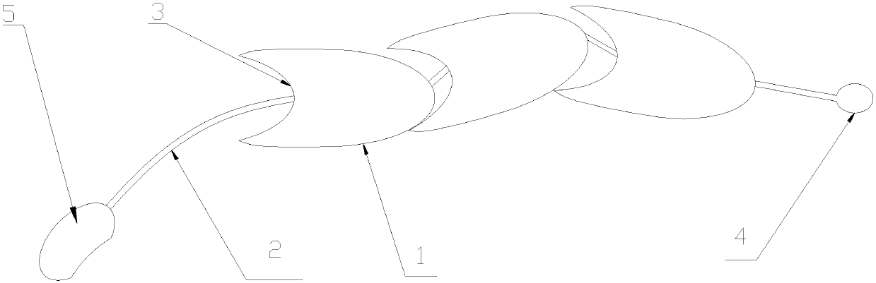
[0054] like figure 1 As shown, in this embodiment, the rapid hemostasis device with an air bag includes a plurality of hemostatic units 1 for hemostasis on wounds, and a flexible hollow connecting tube 2 for passing through each hemostatic unit 1 .

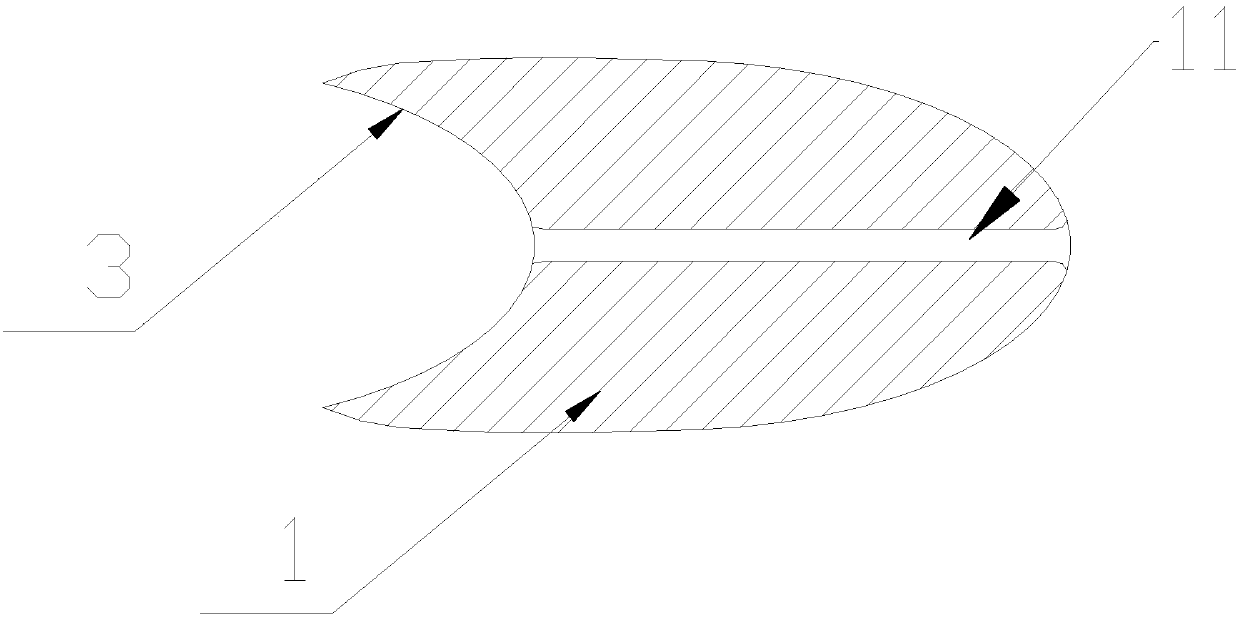
[0055] The inside of each hemostatic unit 1 is provided with a channel 11 that runs through the hemostatic unit 1 and is used for the passage of the connecting tube 2. The head of the hemostatic unit 1 is bullet-shaped, and the tail of the hemostatic unit 1 is correspondingly provided with a The head of a hemostasis unit 1 is inserted into the recessed part 3 .

[0056] The connecting tube 2 is provided with an air bag 4 communicating with the connecting tube 2 at one end located at the top of the hemostasis subunit 7 at the front end. An inflating device 5 is arranged on the end of the connecting pipe 2 away from the air bag 4, and the inflating device 5 is an inflating air bag with a one-way valve inside.

[0057] When hemosta...

Embodiment 2

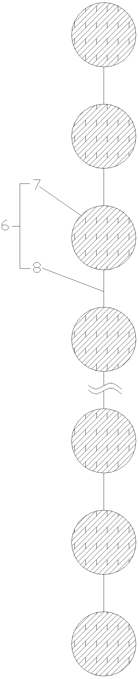
[0060] On the basis of the structure of Embodiment 1, further, the hemostatic unit of this embodiment includes a plurality of hemostatic subunits 7 for hemostasis of the wound; The connection wires 8 between them are connected in series to form a hemostasis chain.

[0061] Further, the partial hemostatic subunit 7 is composed of a hemostatic block 7-1 that absorbs water and expands, and the partial hemostatic subunit 7 is composed of a functional capsule 7-2 for assisting hemostasis.

[0062] The hemostatic subunits 7 are arranged in waves, and the hemostatic subunits 7 are distributed at the crests or troughs;

[0063] The connecting wire 8 is made of insoluble material, and between the adjacent odd-numbered hemostatic sub-units 7 and between the adjacent even-numbered hemostatic sub-units 7 counting from the first hemostatic sub-unit 77 at the beginning are respectively A soluble wire 9 is connected.

Embodiment 3

[0065] On the basis of the foregoing embodiment 1 or 2, further, it is composed of a housing 1-2 with a closed inner cavity 1-1 and a filler located in the inner cavity, and the housing 1-2 is composed of a hemostatic block 7-1 suppressed. The housing includes a front housing 1-2-1 and a rear end cover 1-2-2.

[0066] The filler is composed of multiple functional capsules 7-2 for assisting hemostasis. The functional capsule 7-2 is one or any combination of a decompression capsule filled with gas, a dye capsule filled with dye, or an anti-inflammatory capsule filled with anti-inflammatory drugs. When the hemostatic unit 1 rapidly expands in the wound tract, the functional capsule in the inner cavity is squeezed, and the capsule ruptures, wherein the decompression capsule further releases space for the expansion of the hemostatic material, and adjusts the compressive force of the expansion of the hemostatic material on the wound. Prevent tissue tearing around the wound due to ...


PUM


Abstract

The invention relates to the field of medical equipment, in particular to a rapid bleeding stopping device with an air sac. The rapid bleeding stopping device with the air sac is characterized by comprising a plurality of bleeding stopping units and a flexible hollow connecting tube for penetrating all the bleeding stopping units; each bleeding stopping unit is internally provided with a channel which penetrates through the bleeding stopping unit and is used for penetrating of the connecting tube, the head of each bleeding stopping unit is in a bullet shape, and a sinking part for inserting ofthe head of another bleeding stopping unit is correspondingly arranged at the tail of each bleeding stopping unit; the air sac communicated with the connecting tube is arranged at the top end, in front of the head of a bleeding stopping subunit located at the forefront end, of the connecting tube. The rapid bleeding stopping device with the air sac is suitable for war-injury rapid bleeding stopping, and is particularly suitable for rapid bleeding stopping of foramen-caecum cartridge wounds.

Description

technical field [0001] The invention relates to the field of medical equipment, in particular to a rapid hemostasis device with an air bag. Background technique [0002] Solving the problem of blood loss is still the most urgent problem to be solved in the treatment of war trauma. According to relevant data, cases of uncontrolled massive blood loss account for 90% of retrievable deaths. [0003] At present, the use of tourniquets for hemostasis on the battlefield has the disadvantages of incomplete hemostasis, inconvenient operation, inability to use with one hand, and difficult pressure control and observation. In addition, it is easy to cause severe pain or tissue damage. The distal tissue is prone to ischemic damage after using the tourniquet currently installed by the army, causing tissue necrosis, anaerobic infection, resulting in amputation and even life-threatening. The use of tourniquets on the battlefield was discouraged due to fear of limb necrosis. [0004] From...

Claims


Application Information

Patent Timeline
Patent Type & Authority Applications(China)
IPC IPC(8): A61B17/135
CPCA61B17/1325A61B17/135A61B2017/12004
Inventor 王瑜杨为锦
Owner 王洛
Why Eureka
Try Eureka