Eureka AIR delivers breakthrough ideas for toughest innovation challenges, trusted by R&D personnel around the world.

Transporting and clamping device in column-shaped steel product machining

A clamping device and steel technology, applied in the direction of transportation and packaging, conveyors, conveyor objects, etc., can solve the problems of high labor costs, high investment costs, and low production efficiency of manual operations, so as to improve processing efficiency and reduce costs Effect

Inactive Publication Date: 2018-05-15
东莞市史雷帝三维数控科技有限公司
View PDF0 Cites 7 Cited by
  • Summary
  • Abstract
  • Description
  • Claims
  • Application Information

AI Technical Summary

Problems solved by technology

[0002] With the development of the modern mechanical processing industry, the requirements for steel processing continue to increase, and the requirements for improving production efficiency, reducing production costs, and having highly intelligent automatic cutting functions are also increasing. In the process of mechanical processing, the existing The common method of pipe transportation and clamping is mostly manual, but manual work has low production efficiency and high labor costs
[0003] Under the existing circumstances, in order to realize the assembly line processing of cylindrical steel, it is necessary to rely on large-scale machinery or highly intelligent mechanical arms, and the investment cost is high

Method used


Image

  • Transporting and clamping device in column-shaped steel product machining
  • Transporting and clamping device in column-shaped steel product machining

Examples


Embodiment Construction

[0017] In order to make the technical problems, technical solutions and advantages to be solved by the present invention clearer, the following will describe in detail with reference to the drawings and specific embodiments.

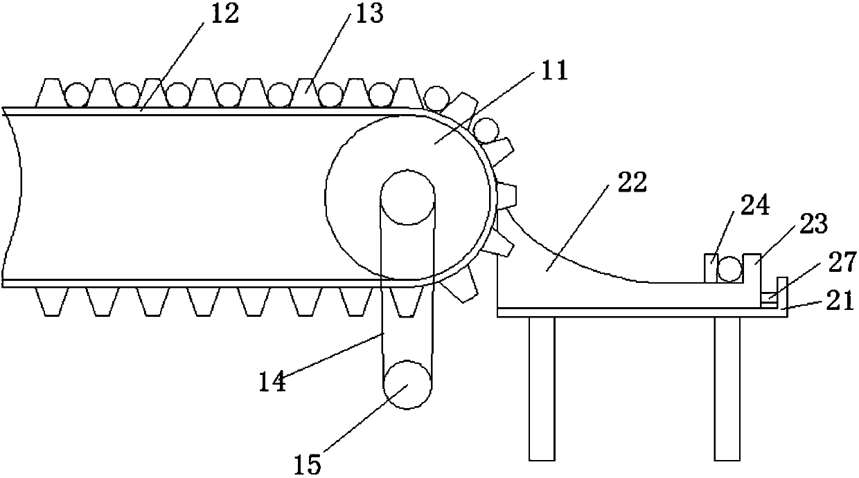
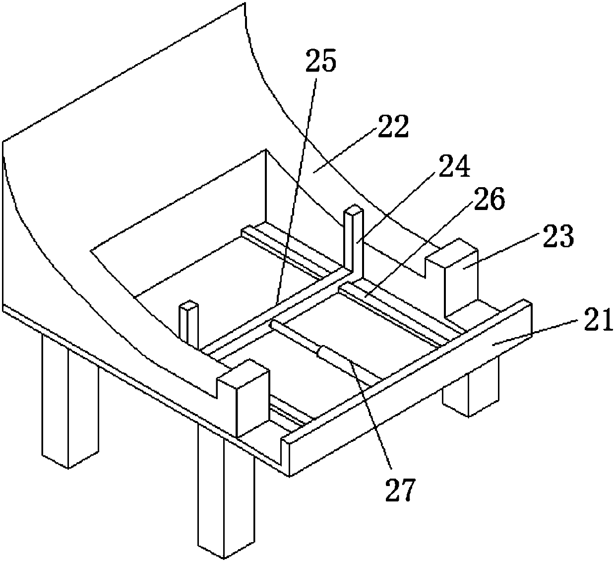
[0018] Such as Figure 1-2 As shown, a transport clamping device in cylindrical steel processing includes a transmission mechanism and a clamping mechanism; the transmission mechanism is composed of a roller 11 and a conveyor belt 12, and the two sides of the conveyor belt 12 are provided with partitions 13 The roller 11 is driven by the motor 15 through the belt 14; the clamping mechanism includes a bracket 21, and the bracket 21 is provided with two tracks 22 parallel to each other, and one end of the track 22 is connected to the transmission mechanism. The discharge end is connected, and the end of the track 22 is provided with a blocking plate 23; a splint 24 is arranged between the two tracks 22, and the top of the splint 24 does not exceed the high...


PUM


Abstract

The invention discloses a transporting and clamping device in column-shaped steel product machining. The transporting and clamping device in the column-shaped steel product machining comprises a conveying mechanism and a clamping mechanism; the conveying mechanism consists of a roller and a conveying belt; separating plates are arranged at the two sides of the conveying belt; the roller is drivenby a motor through a belt; the clamping mechanism comprises a supporting frame and two rails are arranged on the supporting frame in parallel; one ends of the rails are connected with a material discharging end of the conveying mechanism and blocking plates are arranged at the end parts of the rails; a clamping plate is arranged between the rails and the top end of the clamping plate is not higherthan the highest points of the rails; the clamping plate is controlled by a telescoping mechanism; the telescoping mechanism and the motor are controlled by a controlling center and work cooperatively. The device is capable of realizing the automatic transportation and clamping positioning in the steel product machining, low in cost, applicable to moderate and small scale machining enterprises, beneficial to the mechanization and automation in steel product machining and capable of improving the machining efficiency.

Description

technical field [0001] The invention relates to the field of mechanical automation, in particular to a transport clamping device in the processing of cylindrical steel materials. Background technique [0002] With the development of the modern mechanical processing industry, the requirements for steel processing continue to increase, and the requirements for improving production efficiency, reducing production costs, and highly intelligent automatic cutting functions are also increasing. In the process of mechanical processing, the existing The common method of pipe transportation and clamping is mostly manual, however, manual work has low production efficiency and high labor costs. [0003] Under the existing circumstances, in order to realize the assembly line processing of cylindrical steel, it is necessary to rely on large-scale machinery or highly intelligent mechanical arms, and the investment cost is high. Contents of the invention [0004] The purpose of the prese...

Claims


Application Information

Patent Timeline
IPC IPC(8): B65G15/42B65G47/24
CPCB65G15/42B65G47/24
Inventor 覃海莲
Owner 东莞市史雷帝三维数控科技有限公司
Why Eureka
Eureka Blog
Learn More