Top-drawing type pay-off rack

A pay-off frame and frame technology, which is applied in the direction of conveying filamentous materials, thin material processing, transportation and packaging, etc., can solve the problems of messy wires and slow wire speed, and achieve fast wire defense, fast wire defense, and adjustment Convenient and fast effect

Active Publication Date: 2018-05-15
WUXI CHANGXIN TECH
View PDF8 Cites 0 Cited by
  • Summary
  • Abstract
  • Description
  • Claims
  • Application Information

AI Technical Summary

Problems solved by technology

[0003] The current pay-off machines are generally horizontal pay-off, not only the pay-off speed is slow, but also prone to disordered lines

Method used


Image

  • Top-drawing type pay-off rack
  • Top-drawing type pay-off rack

Examples


Embodiment Construction

[0013] The specific embodiments of the present invention will be further described below in conjunction with the accompanying drawings.

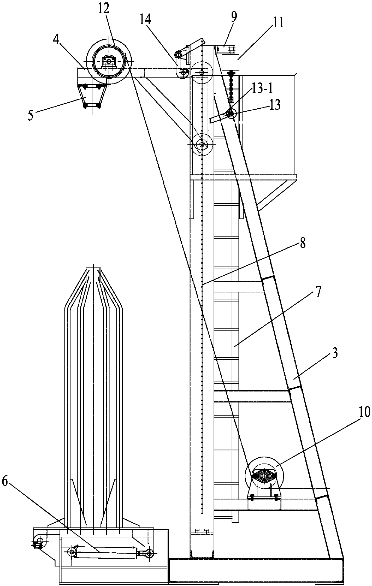
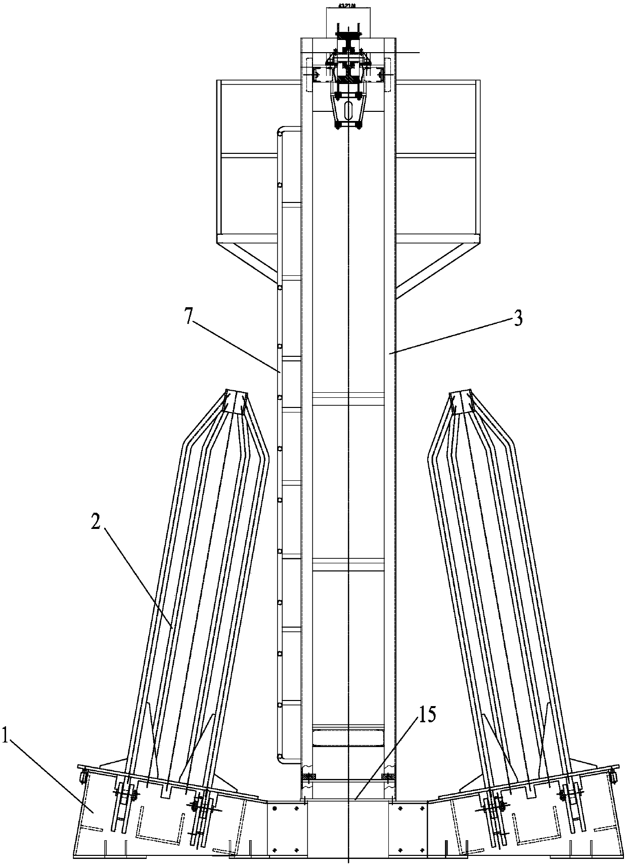
[0014] figure 1 , 2 Among them, including base 1, wire barrel 2, frame 3, lifting frame 4, frame basket 5, hydraulic cylinder 6, ladder 7, iron chain 8, fixed seat 9, guide wheel 2 10, electric hoist 11, guide wheel 1 12 , connecting seat 13, support arm 13-1, hook frame 14, connecting plate 15, etc.

[0015] Such as figure 1 , 2 As shown, the present invention is a kind of upward drawing type pay-off stand, comprises base 1, and frame 3 is installed on the middle platform of base 1, and a wire barrel 2 is respectively hinged on the installation station on both sides of base 1, when in use, wire The cylinder 2 is driven by the hydraulic cylinder 6 installed on the base 1 to rotate around the hinge point; the ladder 7 is installed on the frame 3, the lifting frame 4 is connected to the upper part of the frame 3 in rotation, and an electri...


PUM


Abstract

The invention belongs to the technical field of production of metal products, and relates to a top-drawing type pay-off rack. The top-drawing type pay-off rack comprises a base, wherein a rack is mounted on a platform positioned in the middle of the base; bobbins are respectively hinged to mounting working positions of the two sides of the base; when the top-drawing type pay-off rack is used, thebobbins are driven by a hydraulic cylinder mounted on base to rotate around hinged points; a ladder is mounted on the rack; a lifting rack is connected to the upper part of the rack in a rotating manner; an electric hoist is mounted on the top of the rack; a hook end of the electric hoist is connected with a support arm of a connecting base; the connecting base is fixedly connected with the lifting rack; the upper part of the rack is hinged to a hook rack; a hook of the hook rack is connected with a lifting rod of the lifting rack; the lower end of an iron chain is fixedly connected with the lower part of the rack; the upper end of the iron chain is connected with a driving end of the hook rack; a wire guiding roller I is arranged on the upper surface of the outer end of the lifting rack in a rotating manner; a frame basket is mounted on the lower surface of the outer end of the lifting rack; and a wire guiding roller II is arranged on a mounting stand positioned on the lower part of the rack. According to the pay-off rack disclosed by the invention, paying-off is directly carried out by the bobbins, and the paying-off speed is high so that the phenomenon of disorder of wires is avoided.

Description

technical field [0001] The invention belongs to the technical field of metal product production, and relates to an upward-drawing type pay-off frame. Background technique [0002] In the existing technology, in the metal wire drawing production process, the I-shaped wheel pay-off and the upper draw-off line are the main pay-off forms, but the I-shaped wheel pay-off needs to treat the surface of the wire rod and then collect it on the I-shaped wheel to use. In this process, special equipment and space are needed, resulting in waste. High-level pay-off can be done directly with wire rod, which is relatively simple and saves money. [0003] The current pay-off machines are generally horizontal pay-offs, not only the pay-off speed is slow, but also the phenomenon of disordered wires is more likely to occur. Contents of the invention [0004] Aiming at the above problems, the present invention provides a pull-up type pay-off stand, which is directly paid off from the wire ba...

Claims


Application Information

Patent Timeline
Patent Type & Authority Applications(China)
IPC IPC(8): B65H49/20B65H49/18B65H57/14
CPCB65H49/18B65H49/20B65H57/14
Inventor 袁明
Owner WUXI CHANGXIN TECH
Why Eureka
Try Eureka