Scraped automobile oil collection device

A collection device and technology for scrapped cars, applied in the direction of filtration and separation, only multi-stage series refining process treatment, filtration circuit, etc., can solve the problems of low recovery efficiency, cumbersome treatment process, and large power consumption, so as to improve recovery, Ease of use and high recycling efficiency

Inactive Publication Date: 2018-05-15
荆州市云成汽配有限公司
0 Cites 2 Cited by

AI-Extracted Technical Summary

Problems solved by technology

Existing waste oil recovery can only be collected, and when reused, it needs to be reheated by a heater before filtering, which consumes a lot of power, and the oil temperature is high during filtration, easy to oxidize, the treatment process is cumbersome, and ...

Abstract

The invention discloses a scraped automobile oil collection device which comprises a sliding plate and a waste oil tank, wherein rollers are arranged at the bottom of the sliding plate; the waste oiltank consists of an upper part and a lower part; the upper part is of a square pyramid structure with a larger upper part and a smaller lower part; the lower part is of a square structure; both the upper part and the lower part are of communicated hollow structures; a circular oil outlet is formed in the lower end of the lower part; an oil inlet is formed in the top surface of the upper part. Whenthe scraped automobile oil collection device is used, scraped automobile oil can be greatly recycled, impurities in the scraped automobile oil can be filtered off, and the device is high in recyclingefficiency and convenient to use.

Application Domain

Treatment with plural serial refining stagesFiltration circuits

Technology Topic

Square pyramidFuel tank +3

Image

  • Scraped automobile oil collection device

Examples

  • Experimental program(1)

Example Embodiment

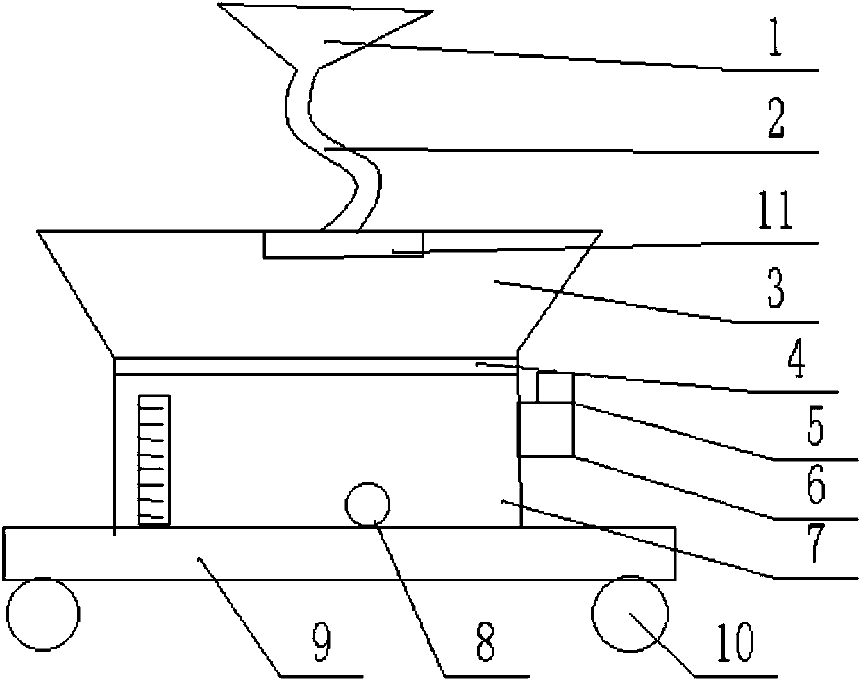
[0017] Such as figure 1 As shown, the present invention provides a scrapped automobile oil collection device, including:
[0018] The sliding plate 9 is provided with a roller 10 at the bottom;
[0019] The waste oil tank is composed of an upper part 3 and a lower part 7. The upper part is a quadrangular pyramid structure with a large upper part and a small lower part, and the lower part is a square structure. The upper part and the lower part 7 are both connected hollow structures, and the lower end of the lower part has The circular oil outlet 8 has an oil inlet on the top surface of the upper part, and the inner side wall of the upper part is provided with a nano coating.
[0020] An oil pumping mechanism, which is composed of a power chamber 6 and a pump 5. The power chamber is in communication with the lower part of the waste oil tank, the pump is in communication with the power chamber, and anhydrous calcium chloride is installed in the power chamber;
[0021] Connecting pipe 2, which is connected with the oil inlet;
[0022] Oil collecting cover 1, which has a funnel-shaped structure, and the oil collecting cover is connected with the connecting pipe;
[0023] The first filter screen 11 is arranged below the oil outlet, and the first filter screen is 20-40 mesh;
[0024] The second filter screen 4 is arranged on the joint surface of the upper and lower parts, and the second filter screen is provided with activated carbon particles.
[0025] The connecting pipe is composed of a hose.
[0026] The waste oil tank is made of transparent material and is marked with scales.
[0027] A rubber ring is embedded in the oil outlet.
[0028] The inner side wall of the upper part is provided with a nano coating.

PUM

no PUM

Description & Claims & Application Information

We can also present the details of the Description, Claims and Application information to help users get a comprehensive understanding of the technical details of the patent, such as background art, summary of invention, brief description of drawings, description of embodiments, and other original content. On the other hand, users can also determine the specific scope of protection of the technology through the list of claims; as well as understand the changes in the life cycle of the technology with the presentation of the patent timeline. Login to view more.

Similar technology patents

Environmentally-friendly degradable paper cup material and preparation method thereof

InactiveCN108951268ALow raw material costimprove recycling
Owner:安徽永豪日用品有限公司

Recycling device of combustible gas in petrochemical gas and recycling method thereof

InactiveCN109973351AImprove air intake efficiencyimprove recycling
Owner:北海市传创环保科技有限公司

Wind turbine generator variable pitch bearing oil collecting tank and recovery system

PendingCN114294189Aimprove recycling
Owner:三峡新能源海上风电运维江苏有限公司

Recovery and utilization of neutralized water in plasticizer DOTP production process

InactiveCN112174411Agood separation effectimprove recycling
Owner:YIXING YANGYANG PLASTIC ADDITIVE

Classification and recommendation of technical efficacy words

  • Improve recycling efficiency
  • improve recycling

Thin-ore-body shallow hole shrinkage method without sill pillar

InactiveCN103089267Aimprove recyclingImprove recovery rate
Owner:ANSTEEL GRP MINING CO LTD

Electricity generation device adopting hollow fiber membrane module as anode of methane-driven microbial fuel cell and electricity generation method

PendingCN111082116AReduce the possibility of leaksimprove recycling
Owner:FUJIAN AGRI & FORESTRY UNIV

Method and apparatus for liquefying a natural gas stream

InactiveCN101156038Aimprove recyclingIncrease production
Owner:SHELL INT RES MAATSCHAPPIJ BV

Waste oil liquid recycling device

InactiveCN108003923Aimprove recyclingImprove recycling efficiency
Owner:荆州市云成汽配有限公司
Why Eureka
Try Eureka