A forced sealing ball valve, valve ball assembly tooling and assembly method
A technology of forced sealing and assembling tooling, applied in valve device, transportation and packaging, cock including cutting device, etc. It can solve the problems of long adjustment process, low efficiency, and inability to guarantee accuracy, saving assembly time and improving economic benefits. , The effect of improving assembly efficiency
- Summary
- Abstract
- Description
- Claims
- Application Information
AI Technical Summary
Problems solved by technology
Method used
Image
Examples
Embodiment 1
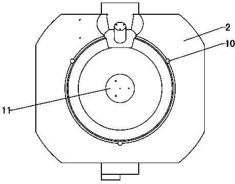
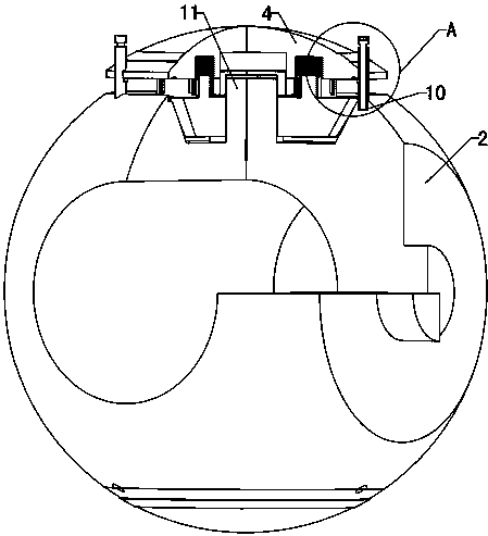
[0044] Refer to attached Figure 1~4 with Figure 8 : A forced seal ball valve, comprising a ball base 2, a disc 4 and a stud gear 1, the stud gear 1 is mounted on the ball base 2 through a stud gear shaft 11, one side of the stud gear 1 passes through a The threaded boss is threadedly connected to the valve clack 4, and more than two positioning holes 10 are correspondingly opened on the contact end surfaces of the valve ball base body 2 and the valve clack 4, and limit pins are installed in the positioning holes 10. The stud gear 1 is connected with the valve stem gear 15 sleeved on the valve stem 14 through the pinion 3 .
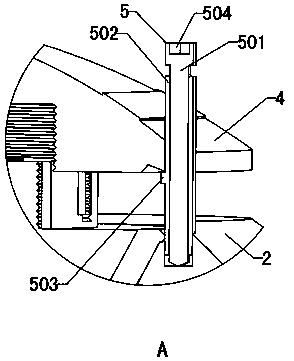
[0045] The utility model relates to a valve ball assembly tool for a forced sealing ball valve, which includes a vertical guide pin and a limit support. The guide pin is provided with a limit support outside, and the top of the guide pin is provided with a rotating part. The guide pin is a sleeve guide pin 5, including a screw 501 and an outer wire sle...
Embodiment 2
[0058] Refer to attached Figure 5 : The rotating part at the top of the top screw 501 in the guide pin is connected to the transmission mechanism, and the transmission mechanism includes the driven gear 6 of the top screw installed on the rotating part and the driving gear 7 meshing with it, and the driving gear 7 is installed on the output shaft of the stepping motor 8 On, the stepper motor 8 is installed on one side of the outer thread sleeve 502. After the steps in step 5 are completed, use the stepping motor 8 and the transmission mechanism to connect the guide pins through the transmission mechanism, and synchronously control the inner jacking wires 501 of the guide pins 501 in the multiple positioning holes 10 to rotate synchronously through the stepping motor 8, so as to lower the position synchronously. The height of the disc support 503 .
[0059] The guide pins are also available in a more automated design driven by stepper motors. Adjust the 3 guide pins to the s...
Embodiment 3
[0061] Refer to attached Image 6 with 7 The guide pin is a stepped guide pin 9, the stepped guide pin 9 includes a cylindrical guide pin body and a plurality of step limit supports 901 arranged on the guide pin body, and the plurality of step limit supports 901 are arranged in a stepped ring on the guide pin On the outside of the body.
[0062] Image 6 , 7 As shown, the guide pin can also adopt an integrated structure with a preset step height. After the stepped guide pin 9 is inserted into the positioning hole 10, as in the first embodiment, the notch of the valve flap 4 is aligned with the stepped guide pin 99, and the valve flap 4 is lowered. Firstly, the step limit support 901 at the highest position is used to support the disc 4. At this time, the thread of the disc 4 is just in contact with the roller 12, and the coincidence of the threaded shaft of the disc with the stud gear shaft 11 and the verticality of the disc 4 are all controlled. Well bound. Rotate the 3...
PUM
 Abstract
Description
Claims
Application Information
 - R&D
- Intellectual Property
- Life Sciences
- Materials
- Tech Scout
- Unparalleled Data Quality
- Higher Quality Content
- 60% Fewer Hallucinations
Browse by: Latest US Patents, China's latest patents, Technical Efficacy Thesaurus, Application Domain, Technology Topic, Popular Technical Reports.
© 2025 PatSnap. All rights reserved.Legal|Privacy policy|Modern Slavery Act Transparency Statement|Sitemap|About US| Contact US: help@patsnap.com


