Dental implants with vibration damping and anti-rotation

A technique for dental implants and implants, which is applied in the fields of dentistry, dental implants, and medical sciences. Bacteria and other problems, to avoid viruses and harmful bacteria, fast assembly, avoid bone resorption

Inactive Publication Date: 2015-10-28
LANZHOU UNIVERSITY
View PDF31 Cites 0 Cited by
  • Summary
  • Abstract
  • Description
  • Claims
  • Application Information

AI Technical Summary

Problems solved by technology

In addition, there is also a hexagonal or octagonal structure for the interposed connection between the implant and the abutment. Such a complex structure is also prone to breeding viruses and harmful bacteria. There are inconveniences, such as: patents such as US 20040209226A1, EP 1679049A1, US 6663388B1 and products such as Frialit-2 and ITI
[0011] (d) In this regard, there are currently few patents and products that consider this aspect of structural design, and some use springs in the implant cavity. On the one hand, the elastic coefficient of the spring will decrease with time, which will affect the function of cushioning and vibration reduction. On the other hand, the contact between the spring and the abutment is not tightly sealed, and the gap left is easy to breed viruses and harmful bacteria, such as: US 19730407244 and other patents
There are also some superelastic materials, memory alloy materials or rubber materials filled in the implant cavity, which will reduce the strength and stability of the superstructure of the implant, such as: US 5174755A, EP 1770302A1, US2009208904A1 and other patents
In addition, these devices cannot effectively achieve the function of releasing rotation while cushioning and reducing vibration.

Method used


Image

  • Dental implants with vibration damping and anti-rotation
  • Dental implants with vibration damping and anti-rotation
  • Dental implants with vibration damping and anti-rotation

Examples


Embodiment Construction

[0036] The preferred embodiments of the present invention will be described below in conjunction with the accompanying drawings. It should be understood that the preferred embodiments described here are only used to illustrate and explain the present invention, and are not intended to limit the present invention.

[0037] The present invention, such as Figure 1-Figure 7 As shown, a dental implant with vibration-reducing and anti-rotation functions is provided,

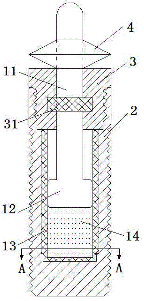
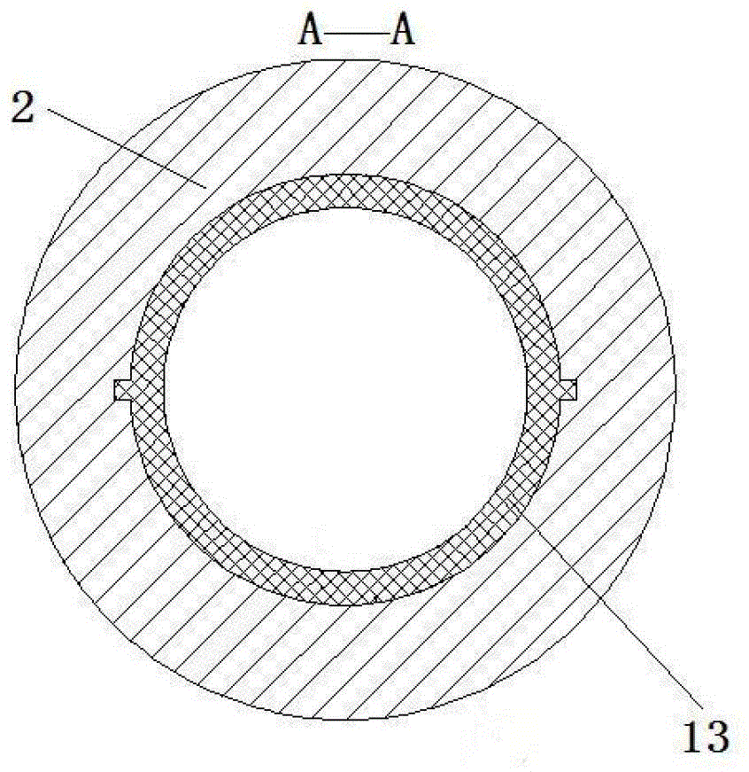
[0038] Such as Figure 1-Figure 7 As shown, the present embodiment includes a shock absorbing component 1 and an implant component 2,

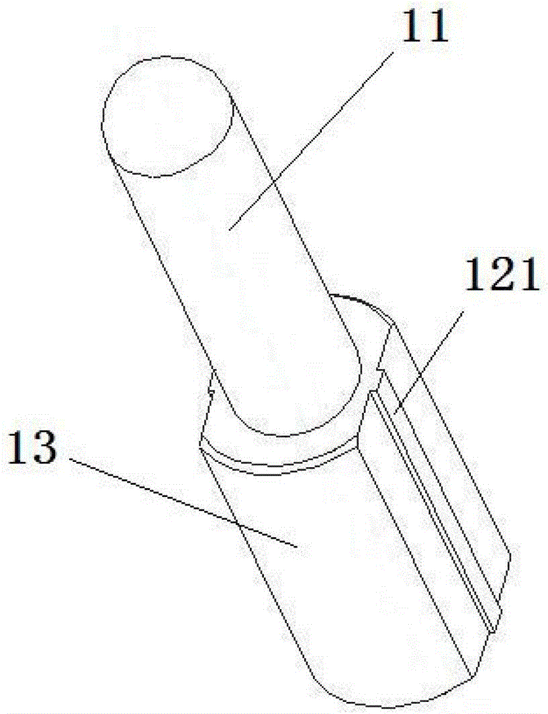
[0039] The buffer and damping component 1 includes a piston rod 11 and an airtight chamber 13,

[0040] The lower end of the piston rod 11 is provided with a piston 12, the piston 12 is inserted into the airtight cavity 13, and the airtight cavity 13 is sealed with air 14,

[0041] The connected piston rod 11 and the airtight cavity 13 are installed in the implant part 2 , and the ...


PUM


Abstract

The invention discloses a dental implant with functions of reducing vibration and preventing rotation, which comprises a buffering and vibration reduction part and an implant part. The buffering and vibration reduction part comprises a piston rod and an airtight cavity; the lower end of the piston rod is provided with a piston; the piston is plugged into the airtight cavity; air is sealed in the airtight cavity; the piston rod and the airtight cavity which are connected are arranged in the implant part; and the outer wall of the airtight cavity is matched with the inner wall of the implant part. The invention provides the artificial dental implant which can be used for effectively buffering the impact and the vibration on teeth, which are generated in the chewing process, dispersing an occlusion load and avoiding the bone adsorption of alveolar bone so as to improve the stability of the implant and also has the characteristics that the dental implant is prevented from rotating, is tightly sealed, is rapid and convenient to assemble, has high strength and the like.

Description

technical field [0001] The invention belongs to the technical field of bone implantation. In particular, it relates to an artificial dental implant. Background technique [0002] As early as 600 AD, the Mayans began to use intraosseous implant technology. It wasn't until Per-Ingvar Branemark used titanium as a material that implantology opened up a new field for modern dentistry. Dental implants, as a new reliable and effective method of oral restoration, have attracted more and more attention in the field of stomatology. [0003] The teeth of a healthy human body are connected to the bone wall of the alveolar socket through the periodontal ligament. The dense connective tissue formed by collagen fibers in the periodontal ligament makes the tooth form a suspension structure in the bone wall of the socket. This suspension structure can effectively Buffer the impact and vibration received by the teeth when chewing food, and disperse the biting pressure transmitted to the al...

Claims


Application Information

Patent Timeline
Patent Type & Authority Patents(China)
IPC IPC(8): A61C8/00
Inventor 周建业陈宏伟王记增周又和李志杰范勤刘斌
Owner LANZHOU UNIVERSITY
Why Eureka
Try Eureka