A non-interference optical gyroscope and rotation sensing method based on a polarization sensing technique

An optical gyroscope and polarization technology, applied in the field of optical fiber information, can solve the problems of increased manufacturing cost, large volume, high device cost, etc.

Inactive Publication Date: 2018-05-15
姚晓天
View PDF6 Cites 13 Cited by
  • Summary
  • Abstract
  • Description
  • Claims
  • Application Information

AI Technical Summary

Problems solved by technology

[0004] Due to the high production cost and large size of the traditional interferometric fiber optic gyroscope, which limits its application in the market, it is currently only used in some special fields (such as military fields, etc.), and it is rarely used in the more common civilian fields.
There are many reasons why the cost of interferometric fiber optic gyroscopes cannot be reduced. On the one hand, the interferometric principle has high requirements for devices, and high performance is required for light sources and modulators, so the cost of devices remains high.
On the other hand, the interferometric cost also has high requirements for the assembly accuracy of the gyroscope, which greatly increases the manufacturing cost, and the yield rate is often relatively low, which is not conducive to automatic mechanical assembly.

Method used


Image

  • A non-interference optical gyroscope and rotation sensing method based on a polarization sensing technique
  • A non-interference optical gyroscope and rotation sensing method based on a polarization sensing technique
  • A non-interference optical gyroscope and rotation sensing method based on a polarization sensing technique

Examples


Embodiment Construction

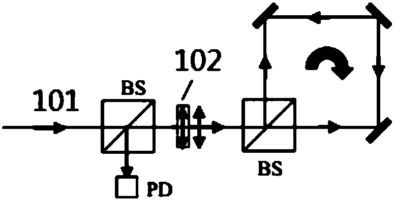
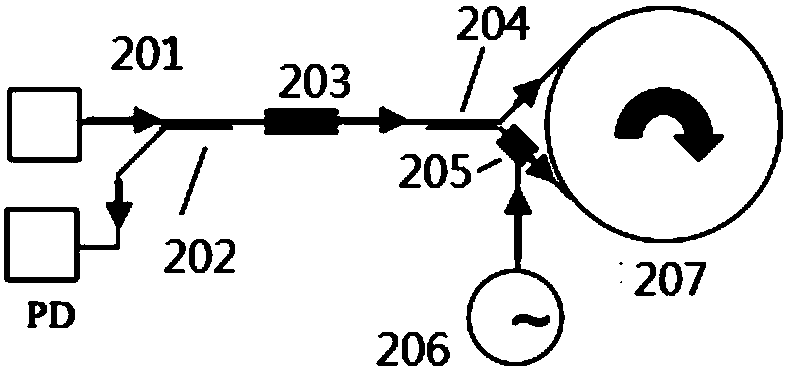
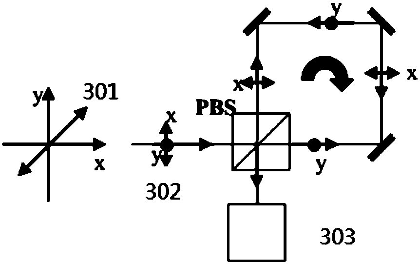
[0044] The present invention discloses optical polarization-based measurement and sensing techniques and devices for optical sensing for sensing rotation that do not use optical interferometry and only detect changes in optical polarization. Using this optical sensing technology and device for optical polarization rotation can make optical gyroscopes widely used, including applications in aircraft, ships and land vehicles, as well as applications in various sensors and devices, such as handheld communication devices, Accurate rotation velocity and angle detection for tablets, smartphones, game controllers, etc.

[0045] In some embodiments of the invention, there is provided a method for sensing rotation based on optical polarization sensing technology without relying on optical interference; polarized light is input into a closed optical loop undergoing rotation, which is closed by coupling Light output from the optical ring circuit; by detecting and processing light polariza...


PUM


Abstract

A non-interference optical gyroscope and rotation sensing method based on a polarization sensing technique are disclosed. The method includes splitting a polarization input beam into a first beam anda second beam, coupling the first and second beams to an input/output ports of an optical loop rotated, with the propagation directions of the first beam and the second beam being contrary; combiningthe first and second beams into a combined beam; detecting polarization information of light output; providing closed feedback loop control by adopting the light output of the optical loop as a feedback so as to generate a feedback control signal; modulating the phase of at least one of the first and second beams into the optical loop by utilizing a phase modulator in a closed feedback loop; applying the feedback control signal to the phase modulator to allow a phase difference between opposite propagation signals in the optical loop to be zero or a difference between the phase difference andzero to be smaller than a preset value; and determining rotation the optical loop had undergone according to the polarization information of light output.

Description

technical field [0001] This patent application belongs to the field of optical fiber information technology, and in particular relates to a method and an optical device for measuring angular rotation information using optical fiber sensing technology. Background technique [0002] Sensing of rotation has a wide range of applications such as navigation, motion sensing, but also stability control and motion control of objects, game console controllers, and smartphone handheld devices. Typically optical gyroscopes can be designed to measure rotation by measuring the change in the optical interference pattern of two counterpropagating beams. Many optical gyroscopes employ optical Sagnac interferometer configurations of various interferometric fiber optic gyroscopes (IFOGs). This optical gyroscope can be designed without moving parts, thereby eliminating the influence of other gyroscopes (such as mechanical gyroscopes) on accuracy and life due to wear and damage of vibrating mas...

Claims


Application Information

Patent Timeline
Patent Type & Authority Applications(China)
IPC IPC(8): G01C19/72
CPCG01C19/72
Inventor 姚晓天
Owner 姚晓天
Why Eureka
Try Eureka