Stranded voltage-resistant optical cable and preparation method thereof

A technology of layer-stranded optical cables, applied in the direction of light guides, optics, optical components, etc., can solve the problems of water seepage in the cable core, slow expansion of water-blocking cable paste, etc., to improve stability, solve the problem of easy aging, and solve the problems of water seepage in the cable core Effect

Inactive Publication Date: 2018-05-15
JIANGSU TRIGIANT OPTOELECTRONICS TECH
View PDF6 Cites 3 Cited by
  • Summary
  • Abstract
  • Description
  • Claims
  • Application Information

AI Technical Summary

Problems solved by technology

[0003] In order to overcome the deficiencies in the prior art, a layer-stranded pressure-resistant optical cable is provided, which solves the problem of water seepage in the cable core by adding the function of the reinforcing member to fill the cable paste, and solves the problem by adjusting the formula of the water-blocking cable paste. Solved the problem of slow expansion of water-blocking cable paste and water seepage in the cable core

Method used


Image

  • Stranded voltage-resistant optical cable and preparation method thereof
  • Stranded voltage-resistant optical cable and preparation method thereof
  • Stranded voltage-resistant optical cable and preparation method thereof

Examples


preparation example Construction

[0032] A method for preparing a layer-stranded pressure-resistant optical cable, comprising the following steps:

[0033] 1) Firstly, select the optical fiber, and select the optical fiber with the required size and performance through the performance inspection of the optical fiber. Set the pay-off tension of the optical fiber as: 80g±10g, set the take-up tension as: 60g±5g, and set the mold For: the inlet mold is 260um and the outlet mold is 254um, to ensure that the diameter of the fiber after coloring is maintained at: 252~260um;

[0034] 2) Then the optical fiber is colored, by setting the curing power of the curing furnace at the actual production speed to 100%, selecting a 10-inch UV lamp with a power of 6000W, and ensuring that the nitrogen pressure in the curing furnace during the production process is ≥ 2.5 m3 / h to ensure The absolute curing degree of colored optical fiber is above 95%;

[0035] 3) Preheat the optical fiber, preheat the optical fiber for 2 hours, th...

Embodiment 1

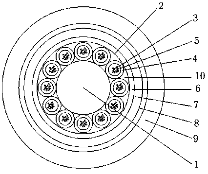
[0043] A method for preparing a layer-stranded pressure-resistant optical cable. The specific steps are: screening optical fibers, optical fiber coloring, secondary coating of optical fibers, cable forming, inner sheath extrusion, outer sheath extrusion, and finished product inspection.

[0044] Preferably, through the inspection of optical fiber performance, the optical fiber with required size and performance is screened out, and the indicators are as follows.

[0045]

[0046] Preferably, the pay-off tension of the optical fiber is set to 80g±10g, the take-up tension is set to 60g±5g, and the mold is set to: the inlet mold is 260um and the outlet mold is 254um, so as to ensure the diameter of the optical fiber after coloring Maintain at: 252 ~ 260 um, by reducing the diameter of the fiber to achieve the purpose of reducing the duty cycle of the fiber in the loose tube.

[0047] Preferably, by setting the curing power of the curing furnace at the actual production speed t...


PUM


Abstract

The invention discloses a stranded voltage-resistant optical cable and a preparation method thereof. The stranded voltage-resistant optical cable comprises a central reinforced core located in the center of an optical cable, and an optical fiber unit layer is arranged outside the central reinforced core; and the optical fiber unit layer is externally lapped with an aluminum-plastic composite tape,the aluminum-plastic composite tape is externally wrapped with a polyethylene inner protecting jacket in an extrusion manner, the polyethylene inner protecting jacket is externally lapped with a steel-plastic composite tape, and the steel-plastic composite tape is externally wrapped with a polyethylene outer protecting jacket in an extrusion manner. By increasing a reinforce cable paste filling function, the water seepage problem of the cable core is solved; and by adjusting the formula of water-blockage cable paste, the problems that a water-blockage cable slowly expands, and water seeps from the cable core are solved.

Description

technical field [0001] The invention relates to an optical cable and a production method thereof, in particular to a layer-stranded pressure-resistant optical cable and a preparation method thereof, belonging to the technical field of optical fiber cable preparation. Background technique [0002] With the continuous advancement of fiber-to-the-home, optical cables have been widely used. Compared with duct optical cables, direct-buried optical cables have the advantages of low construction cost, good security and confidentiality, and simple construction during the laying process. It is difficult to maintain and troubleshoot faults, so the optical cable must be able to withstand large lateral pressure and tension, adapt to a large range of temperature changes, and be waterproof and rodent-proof. Contents of the invention [0003] In order to overcome the deficiencies in the prior art, a layer-stranded pressure-resistant optical cable is provided, which solves the problem of ...

Claims


Application Information

Patent Timeline
Patent Type & Authority Applications(China)
IPC IPC(8): G02B6/44
CPCG02B6/443G02B6/4434G02B6/4482G02B6/4486G02B6/44384
Inventor 潘家乐常国庆代庸宗俊臣蒋淼
Owner JIANGSU TRIGIANT OPTOELECTRONICS TECH
Why Eureka
Try Eureka