
Processing equipment for high frequency transformers

A technology for high-frequency transformers and processing equipment, applied in the direction of transformers/inductor coils/windings/connections, chemical instruments and methods, cleaning methods using gas flow, etc., can solve the problem of damaged pins and transformer soldering, manual alignment Good, low efficiency of manual straightening, etc., to achieve the effect of reducing manual operation, reducing the defective rate of transformers, and facilitating straightening

Inactive Publication Date: 2019-04-02
湖南万安达(集团)米江农工贸有限责任公司
View PDF6 Cites 0 Cited by
  • Summary
  • Abstract
  • Description
  • Claims
  • Application Information

AI Technical Summary

Problems solved by technology

[0005] The calibration tools and calibration methods in the prior art have the following defects: 1. It is easy to pull out the pins from the transformer body, or damage the solder connecting the pins to the transformer, or scratch the surface of the pins, which improves the quality of the transformer. Defective rate; 2. The effect of manual straightening is not good; 3. The efficiency of manual straightening is low, and the labor cost is high

Method used


Image

  • Processing equipment for high frequency transformers
  • Processing equipment for high frequency transformers

Examples


Embodiment Construction

[0024] Further detailed explanation through specific implementation mode below:

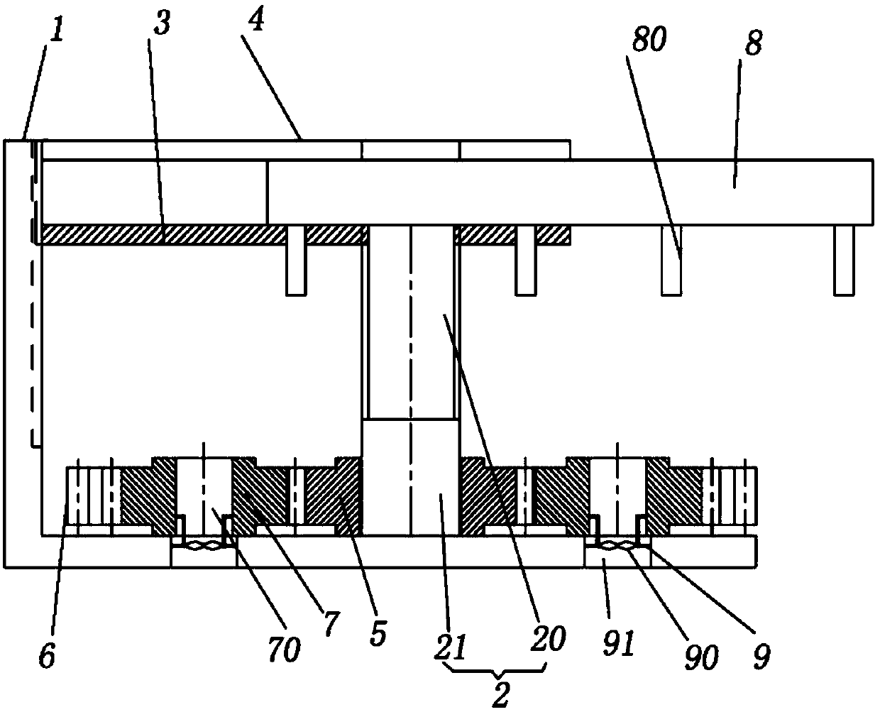
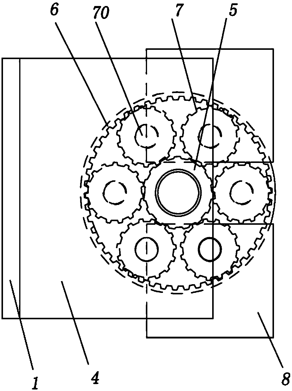
[0025] The reference signs in the drawings of the description include: frame 1, rotating shaft 2, threaded section 20, smooth surface section 21, threaded cover 3, buckle plate 4, transmission hub 5, support hub 6, rotating hub 7, alignment hole 70 , Transformer body 8, pin 80, support frame 9, negative pressure blade 90, dust removal hole 91.

[0026] The embodiment is basically as attached figure 1 Shown: Processing equipment for high-frequency transformers, including frame 1, motor, lifting mechanism and straightening mechanism.

[0027] Frame 1 is " L " shape, is provided with chute in its vertical part.

[0028] The lifting mechanism includes a rotating shaft 2 and a support cover for fixing the transformer body 8 . The rotating shaft 2 includes a threaded section 20 at the top and a smooth section 21 at the bottom, and the output shaft of the motor is coaxially connected with the bottom ...


PUM


Abstract

The invention belongs to the technical field of electronic component preparation, and particularly relates to high-frequency transformer machining equipment. The high-frequency transformer machining equipment comprises a machine frame, a motor, a lifting mechanism and an straightening mechanism; the lifting mechanism includes a rotating shaft and a supporting cover for moving a transformer up anddown, the rotating shaft includes a threaded section and a smooth surface section, the supporting cover is in threaded connection with the threaded section of the rotating shaft, the supporting coveris vertically and slidably connected with the machine frame, and an output shaft of the motor is connected with the rotating shaft; the straightening mechanism includes a transmission hub, a supporting hub and rotating hubs, one sides of the rotating hubs are meshed with the supporting hub, the other sides of the rotating hubs are meshed with the transmission hub, and the transmission hub is fixedly connected with the smooth surface section of the rotating shaft; and straightening holes for straightening pins are formed in the rotating hubs. According to the technical scheme of the high-frequency transformer machining equipment, the pins can be effectively prevented from being pulled out and scratched or soldering tin is prevented from being damaged during straightening, the defective rateof products is decreased, and the straightening effect is improved.

Description

technical field [0001] The invention belongs to the technical field of electronic component preparation, and in particular relates to processing equipment for high-frequency transformers. Background technique [0002] High-frequency transformer is a power transformer whose working frequency exceeds intermediate frequency (10kHz). It is mainly used as high-frequency switching power transformer in high-frequency switching power supply, and also used as high-frequency inverter in high-frequency inverter power supply and high-frequency inverter welding machine. The high-frequency transformer is the most important part of the switching power supply. Generally speaking, a high-frequency transformer includes a high-frequency transformer body and pins connected to the bottom of the high-frequency transformer body, and the pins and the transformer body are connected by soldering tin. The number of pins depends on the specific needs of use. The most widely used pins are 8, which are ...

Claims


Application Information

Patent Timeline
Patent Type & Authority Patents(China)
IPC IPC(8): B21F1/02B08B5/02H01F27/29
CPCB08B5/02B21F1/02H01F27/29
Inventor 佘加旭
Owner 湖南万安达(集团)米江农工贸有限责任公司
Learn More