Adhesive Corner Prefabrication and Integrated Infusion Molding Process

A technology of infusion molding and bonding angle, which is applied to household appliances, other household appliances, household components, etc., can solve the problems of long blade production cycle, difficult observation of the trailing edge glue, easy to blow up, etc., so as to reduce the flow time of the blade. , The effect of avoiding tooling indentation defects and improving product qualification rate

Active Publication Date: 2020-06-09
SINOMATECH JIUQUAN WIND POWER BLADE CO LTD
View PDF3 Cites 0 Cited by
  • Summary
  • Abstract
  • Description
  • Claims
  • Application Information

AI Technical Summary

Problems solved by technology

This molding process has the following disadvantages: (1) During the laying process, because the trailing edge has a larger arc than the front edge, the bonding angle of the trailing edge has a larger arc, the cloth layer is not easy to fit the tooling, and the cloth layer is not easy to adjust , wasting a lot of man-hours; (2) Because the width of the bonding angle at the trailing edge is wider than that of the rubber, and tooling needs to be placed during the molding process, the vacuum film is not easy to adjust when vacuuming, and the vacuum film is prone to be suspended. It is easy to pump and cause air leakage; (3) During the infusion process, due to the uniaxial layer on the rear edge, the glue is slow, and the bonding angle of the rear edge needs to be infused, resulting in a large amount of infusion resin; and the glue on the rear edge Difficult to observe; (4) If the trailing edge bonding angle forming tooling adopts a positive mold, it is easy to form steps in the uniaxial layer area on the edge of the tooling, and the maintenance cost is high; (5) After forming, the bonding angle is prone to wrinkles, steps, etc. Defects, long maintenance time, longer blade production cycle; and due to the restriction of the trailing edge cavity, the defect is not easy to identify, so there is a greater quality risk; (6) After the skin is cured, it is difficult to clean the tooling and auxiliary materials at the bonding angle big, wastes a lot of time

Method used


Image

  • Adhesive Corner Prefabrication and Integrated Infusion Molding Process
  • Adhesive Corner Prefabrication and Integrated Infusion Molding Process
  • Adhesive Corner Prefabrication and Integrated Infusion Molding Process

Examples


Embodiment

[0026] Embodiment: Taking the production of megawatt-level wind power blades with a length of 54.38m as an example

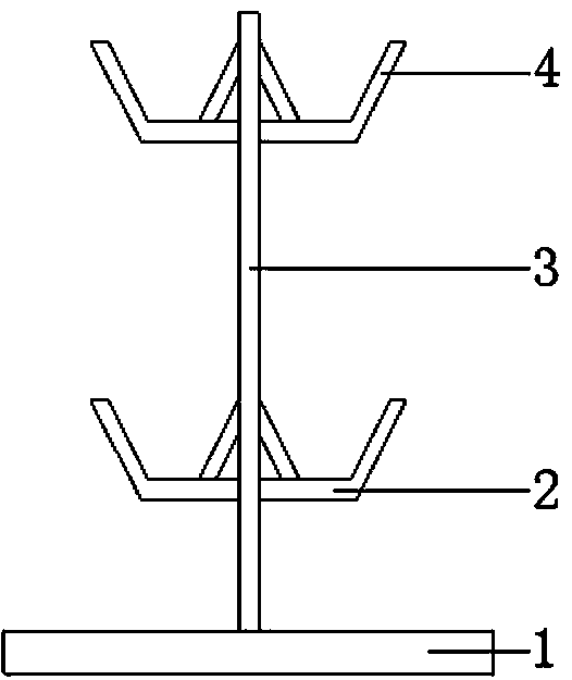
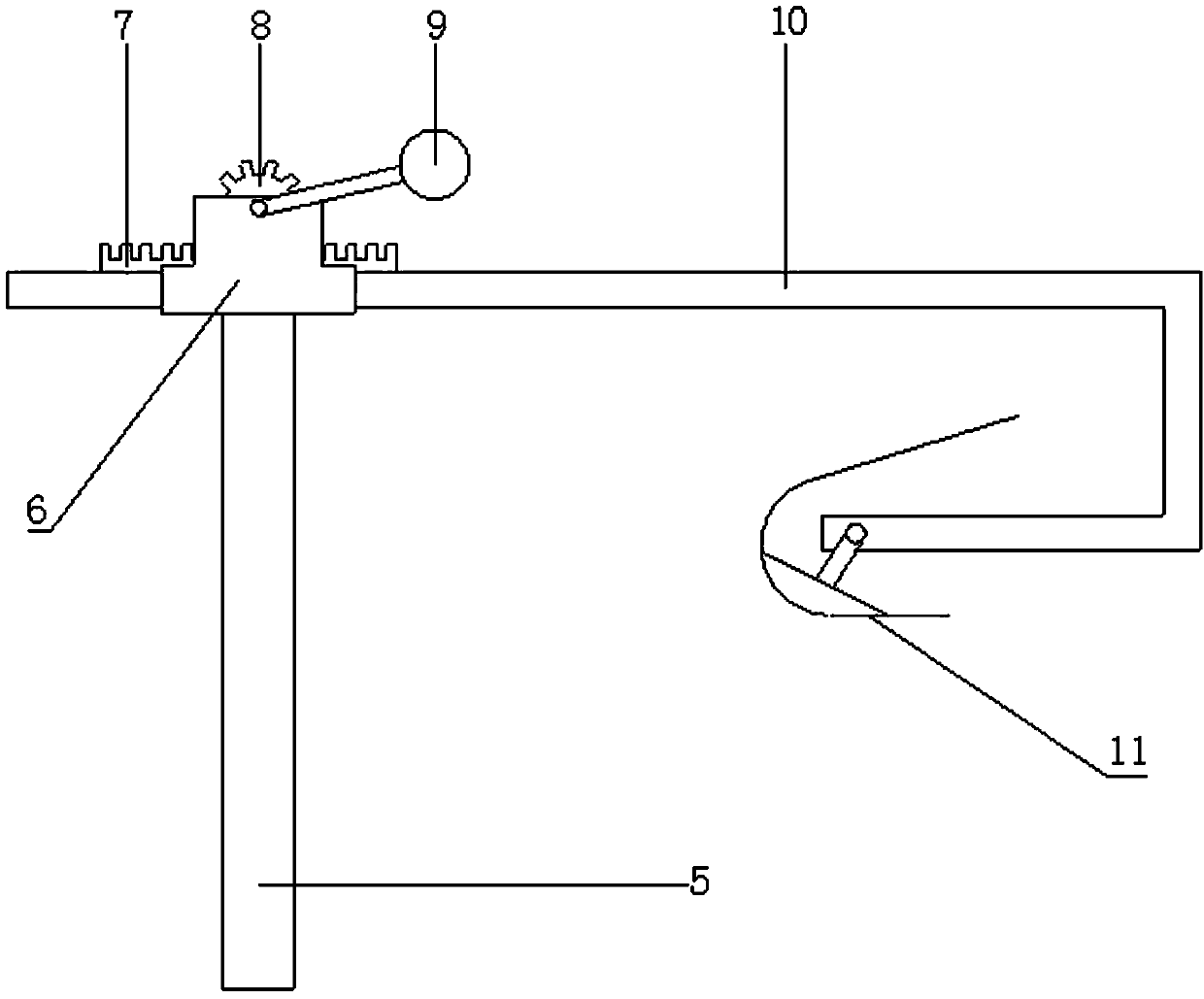
[0027] (1) Fabrication of adhesive angle molds: maintain the adhesive angle structure, divide the adhesive angle simulated cloth layer into two according to the clamping seam, and then lay and pour them on the windward side and the leeward side of the mold with skin; Surface bonding angle simulates the cloth layer and scrapes the triangle rubber type with a thickness of 2.0-4.0mm and a width of 30-50mm, and then glues the windward side to the mold. After curing, the mold is demoulded to obtain the male mold; use an angle grinder 1. Clean the burrs on the inner side of the male mold with a peak steel knife, apply a release agent, lay a porous film, cut the glass fiber cloth and pour it into the mold, and heat and cure it to demould to obtain a prefabricated mold for the bonding angle;

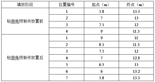
[0028] (2) Bonding angle prefabrication: use the bonding angle prefabricated ...


PUM

PropertyMeasurementUnit
widthaaaaaaaaaa
widthaaaaaaaaaa
lengthaaaaaaaaaa

Abstract

The invention provides a bonding corner prefabricating and integrated filling forming process. The bonding corner prefabricating and integral filling forming process comprises the steps of manufacturing a bonding corner mold, prefabricating a bonding corner, carrying out skin forming and carrying out integrated filling. According to the bonding corner prefabricating and integral filling forming process, in a blade forming process, the bonding corner prefabricating and skin forming integrated filling technology is adopted, due to the fact that a bonding corner prefabricated part is manufacturedin advance, the defect of a bonding corner is easy to control and recognize, and the found defect can be maintained effectively in time; moreover, a bonding corner cloth layer does not need to be coated with resin and soaked again in a filling process, so that the filling time is effectively shortened, the use amount of filling resin is reduced, the production cost is reduced while the productionefficiency is improved, and the product percent of pass is improved; due to the fact that the bonding corner defect is recognized in a prefabricating stage, the defect maintenance phenomenon can notbe found again during subsequent-stage circulation, secondary maintenance at a main forming stage is avoided, and the blade circulation time is shortened; and therefore, the production efficiency is improved, and a considerable popularization prospect and potential practical value are achieved.

Description

technical field [0001] The invention relates to the technical field of production of wind power blades, in particular to prefabrication of bonding angles and integral pouring molding processes. Background technique [0002] In the existing wind power blade forming technology, the forming method of the front and rear edge bonding angles is as follows: during the skin forming process, the trailing edge bonding angle cloth layer is laid together with the skin cloth layer, depending on the positioning of the bonding angle tooling The cloth layer, the control glue layer, the adhesive corner cloth layer and the skin cloth layer are poured and formed together. This molding process has the following disadvantages: (1) During the laying process, because the trailing edge has a larger arc than the front edge, the bonding angle of the trailing edge has a larger arc, the cloth layer is not easy to fit the tooling, and the cloth layer is not easy to adjust , wasting a lot of man-hours; ...

Claims


Application Information

Patent Timeline
Patent Type & Authority Patents(China)
IPC IPC(8): B29C70/68B29C70/34B29C70/44B29B11/06B29L31/08
CPCB29B11/06B29C70/342B29C70/44B29C70/68B29C70/681B29C70/683B29L2031/085
Inventor 文景波张万娟王国伟田军董勃刘锦帆权飞
Owner SINOMATECH JIUQUAN WIND POWER BLADE CO LTD
Why Eureka
Try Eureka