Thin film conveying deviation correction structure and control method

A control method and film technology, which is applied in thin material processing, winding strips, transportation and packaging, etc., can solve problems such as equipment failure downtime, complex deviation correction process, large film position deviation, etc., to achieve accurate transmission and deviation correction, and improve The effect of product quality and simple structure

Pending Publication Date: 2018-05-18
HONGTA TOBACCO GRP
View PDF5 Cites 1 Cited by
  • Summary
  • Abstract
  • Description
  • Claims
  • Application Information

AI Technical Summary

Problems solved by technology

[0004] Other equipment, such as cigarette product packaging machines, have film conveying mechanisms, but these mechanisms have the following three common defects: 1) It is impossible to adjust and control the position of the film on the conveying roller, and the film will appear on the conveying roller during the film conveying process. Position deviation, because there is no deviation correction function, the position deviation of the film will become larger and larger, which will eventually cause the equipment to stop. 3) The detector is configured to detect the position of the film on the conveying roller in real time and has a deviation correction function, but the deviation correction process is complicated and requires a set of linkage of multiple transmission rollers to achieve correction
[0005] Therefore, the film transmission mechanism in the above existing equipment cannot satisfy the stable and accurate transmission of the polylactic acid film on the forming machine, and cannot guarantee the batch production of filter rods for heat-not-burn tobacco products

Method used


Image

  • Thin film conveying deviation correction structure and control method
  • Thin film conveying deviation correction structure and control method
  • Thin film conveying deviation correction structure and control method

Examples


Embodiment Construction

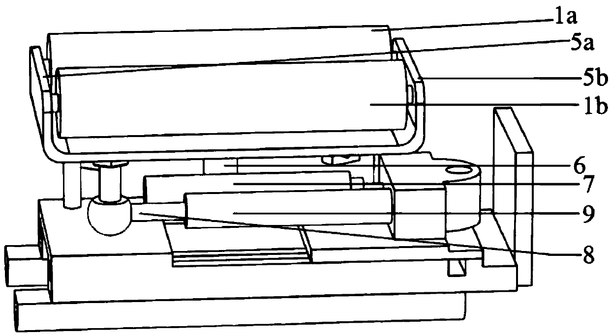
[0028] As shown in the figure, the correcting roller mount 5a and the correcting roller mount 5b are used to install two correcting rollers 1a, 1b and the telescopic rod 8 in parallel; Distance: One end of the telescopic rod 8 is connected to the deviation-correcting roller mounting seat 5a, and one end is installed in the sleeve 9, and the entire deviation-correcting roller mounting seat can move left and right around the rotating shaft 6 of the deviation-correcting roller mounting seat.

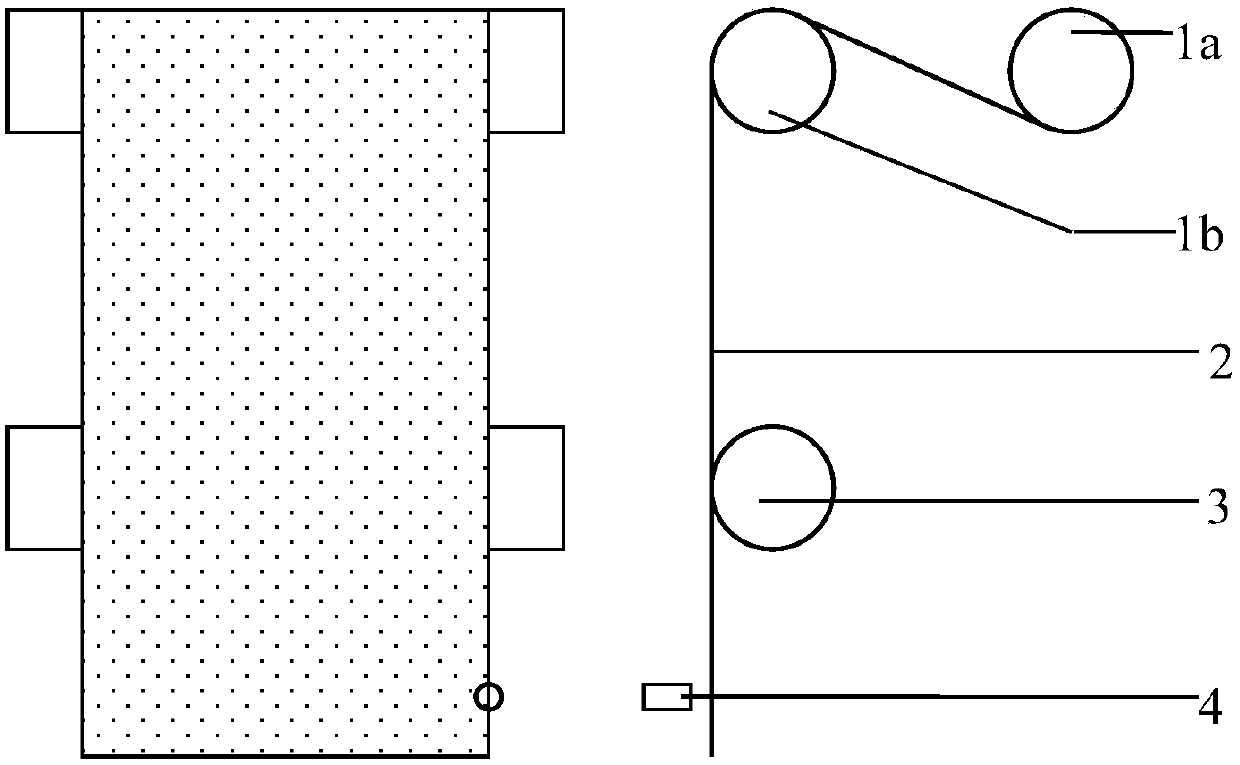
[0029] Such as figure 1 As shown, the film 2 is conveyed through the correction roller 1a, the correction roller 1b and the conveying roller 3, and the film conveying position detector 4 detects the conveying position of the film 2 on the conveying roller 3 in real time.

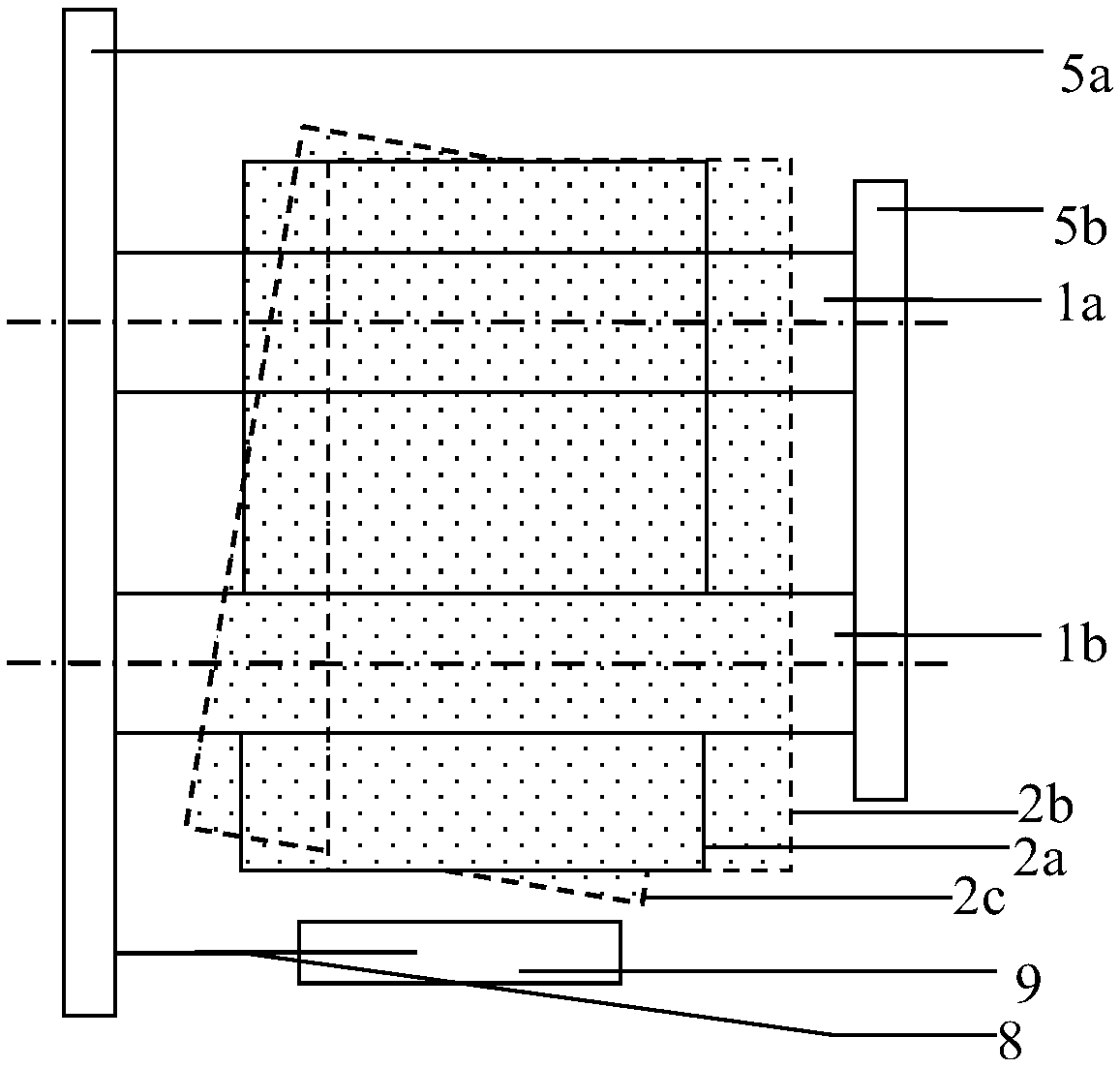
[0030] When the film conveying position detector 4 detects that the position of the film on the conveying roller 1 deviates, as image 3 , the film shifts to the right from the given transfer position 2a to 2b, the detec...


PUM


Abstract

The invention discloses a thin film conveying deviation correction structure and control method, and particularly relates to a thin film conveying deviation correction mechanism arranged on a filter rod forming machine and a corresponding deviation correction control method. The deviation correction mechanism is mainly composed of a detector, deviation correction rollers, deviation correction roller mounting seats and a telescopic rod. When the deviation correction roller mounting seats rotate clockwise or anticlockwise under the stretching or retracting acting force of the telescopic rod, thedeviation correction rollers rotate therewith; and in the rotating process of the deviation correction rollers, a thin film wound around the deviation correction rollers can generate leftward or rightward displacement (anticlockwise or clockwise angular displacement), and therefore leftward or rightward friction force (anticlockwise or clockwise friction moment) is generated to the thin film, thethin film is driven to move leftwards or rightwards (rotate anticlockwise or clockwise), and the function of deviation correction is achieved. The deviation correction structure is compact, manufacturing and mounting are easy, the control method is simple, the thin film can be stably and precisely conveyed at the conveying roller given position in the conveying process, and the best conveying effect is obtained.

Description

technical field [0001] The invention belongs to the technical field of rod forming in the tobacco industry, in particular to a film transmission deviation correction structure and a control method thereof, which are used for adjusting and controlling the position of the film on the transmission roller. Background technique [0002] With the improvement of living standards, reducing the harmfulness of cigarettes has become the core task of the sustainable development of the tobacco industry. New heat-not-burn tobacco products are closer to traditional cigarettes in terms of physiological feelings, psychological perception, and smoking methods, and have obvious harm reduction characteristics. getting more popular. [0003] When making heat-not-burn tobacco products, it is necessary to use polylactic acid film material (PLA) to make filter rods to reduce the temperature of the inhaled airflow. However, there is no polylactic acid film material (PLA) filter rod forming technolo...

Claims


Application Information

Patent Timeline
Patent Type & Authority Applications(China)
IPC IPC(8): B65H23/038
CPCB65H23/038B65H2701/1752B65H2801/54
Inventor 覃志宏马晓伟周波张凌王俊潘永华吴杰甘志高杨宇恒李文逢韩敬美王跃琼马璇
Owner HONGTA TOBACCO GRP
Why Eureka
Try Eureka