Passing type steel pipe hardening and tempering production line and application method thereof

A production line and steel pipe technology, applied in the field of pass-through steel pipe quenching and tempering production line, can solve the problems of backflow to the quenching furnace and quenching water splash, and achieve the effect of protecting personnel safety, ensuring quenching quality, and good working environment for workers

Pending Publication Date: 2018-05-18
CHINA NAT HEAVY MACHINERY RES INSTCO
View PDF6 Cites 1 Cited by
  • Summary
  • Abstract
  • Description
  • Claims
  • Application Information

AI Technical Summary

Problems solved by technology

[0004] The purpose of the present invention is to provide a through-type steel pipe quenching and tempering production line and its application method, which can overcome the problems of quenching water splashing and backflow back to the quenching furnace in the existing steel pipe quenching and tempering production line

Method used


Image

  • Passing type steel pipe hardening and tempering production line and application method thereof
  • Passing type steel pipe hardening and tempering production line and application method thereof
  • Passing type steel pipe hardening and tempering production line and application method thereof

Examples


Embodiment 1

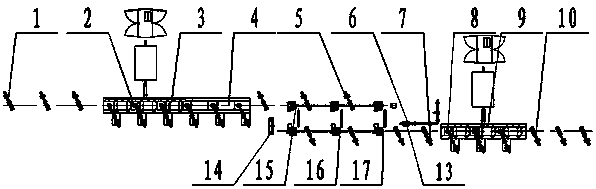
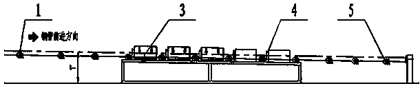
[0026] This embodiment provides a figure 1 , figure 2 and image 3 The through-type steel pipe quenching and tempering production line shown includes a quenching furnace 3 and a tempering furnace 9. The quenching furnace 3 is laid along a straight line from the entrance to the exit. 5. A pass-through annular quenching device 4 is installed on the quenching roller table 2, and a water blowing device 6 is installed at the 5 place of the quenching furnace exit roller table; Fire roller table 8, tempering furnace discharge roller table 10.

[0027] The working process of the through-type steel pipe quenching and tempering production line is as follows:

[0028] The steel pipe is transported to the quenching furnace 3 through the quenching furnace entering roller table 1, transported by the quenching roller table 2 to the quenching furnace 3 for heating, and quenched by the ring quenching device 4, and then the steel pipe is output from the quenching furnace by the roller table...

Embodiment 2

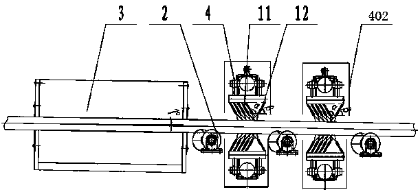
[0030] On the basis of Example 1, such as Figure 4 and Figure 5 As shown, the through-type annular quenching device 4 includes a water spray ring 401, a frame 404 and a conveying roller table 403 driven by a motor. The water spray ring 401 is vertically installed on the frame 404, and the conveying roller table 403 is perpendicular to the spraying roller The central axis of the water ring 401 is placed on the ground, and the conveying roller table 403 is located below the central axis of the water spray ring 401. The water spray ring 401 includes a water supply pipe 4011, which is an annular steel pipe, and several The branch pipe 4010 communicated with the annular steel pipe, the branch pipe 4010 is vertically connected to the swing arm 409, one end of the swing arm is driven by the power unit 4012, and the other end is connected to the nozzle main pipe 408, and several nozzles 407 are installed at the end of the nozzle main pipe 408.

[0031] The working process of passin...

Embodiment 3

[0035] On the basis of Embodiment 2, the through-type annular quenching device 4 also includes a machine cover 402 that is covered on the water spray ring 401 to prevent the quenching water from splashing everywhere, and the frame 404 and the machine cover 402 cover the water spray ring together to prevent The quenching water is splashed everywhere; the lower surface of the frame 404 is perforated and the deflector 4014 is welded to guide the quenching water. A water tank 406 is arranged below the deflector 4014, and the quenching water is introduced into the water tank 406. The bottom of the frame 404 is installed with a lifting guide device 405 that drives its lifting. It should be noted that the lifting guide device 405 is an existing structure. As a preference, the present embodiment selects an oil cylinder or an electric push rod, and the lifting guide device 405 drives Frame 404 is integrally lifted, so that the water spray ring, the machine cover and the frame are lifted...


PUM


Abstract

The invention relates to a passing type steel pipe hardening and tempering production line and an application method thereof. The production line comprises a furnace entering roller way of a quenchingfurnace, a quenching roller way, the quenching furnace, an annular quenching device, a furnace discharging roller way of the quenching furnace, a water blowing device, a furnace entering roller way of a tempering furnace, a tempering roller way, the tempering furnace and a furnace discharging roller way of the tempering furnace, wherein a steel pipe is conveyed into the quenching furnace throughthe furnace entering roller way of the quenching furnace, and is heated in the quenching furnace; the annular quenching device performs quenching; then, the steel pipe is output from the furnace discharging roller way of the tempering furnace; the water blowing device dries the cooling water on the surface of the steel pipe through blowing and then performs tempering through being conveyed into the tempering furnace to be tempered from the furnace entering roller way of the quenching furnace and the tempering roller way; the steel pipe is then output from the furnace discharging roller way ofthe tempering furnace. The production line has the advantages that the structure is simple; the investment cost is low; the occupied area is small; the furnace entering roller way of the quenching furnace, the quenching roller way, the quenching furnace and the furnace discharging roller way of the quenching furnace are in inclined arrangement in a way of forming an angle being 1 degree; a spray nozzle of the annular quenching device and the steel pipe operation direction are respectively inclined for 5 degrees; quenching water sputtering and backflow into the quenching furnace can be prevented; the quenching furnace is protected; the steel pipe quenching quality is ensured.

Description

technical field [0001] The invention belongs to the technical field of steel pipe heat treatment, and in particular relates to a through-type steel pipe quenching and tempering production line and an application method. Background technique [0002] The steel pipe quenching and tempering process is the most typical heat treatment process, that is, the process of quenching and tempering the steel pipe. The steel pipe is quenched to obtain as much martensite as possible, and then tempered at high temperature to finally obtain tempered sorbite, so that the mechanical properties of the steel pipe can be optimized. [0003] In the steel pipe quenching and tempering process, the main equipment includes quenching furnace, quenching device and tempering furnace. There are three types of quenching furnace and tempering furnace, walking type, roller hearth type and medium frequency induction heating furnace. There are also three types of quenching devices, outer shower-inner spray q...

Claims


Application Information

Patent Timeline
Patent Type & Authority Applications(China)
IPC IPC(8): C21D1/25C21D1/667C21D9/08
CPCC21D1/25C21D1/667C21D9/0062C21D9/08C21D2211/009
Inventor 高璐杜学斌徐能惠李永辉任明杰马辉高国杰
Owner CHINA NAT HEAVY MACHINERY RES INSTCO
Why Eureka
Try Eureka