Quenching device for tooth surface of chain wheel

A technology of quenching device and sprocket teeth, applied in the direction of quenching device, furnace type, furnace, etc., can solve the problems of easy oxidation of sprocket tooth surface, long production process time, difficult quality assurance, etc., and achieve short production process and simple structure , the effect of improving production efficiency

Active Publication Date: 2012-12-05
山东开泰工业科技有限公司
View PDF0 Cites 1 Cited by
  • Summary
  • Abstract
  • Description
  • Claims
  • Application Information

AI Technical Summary

Problems solved by technology

[0002] At present, most of the sprocket tooth surface quenching is divided into two steps of heating and cooling. First, the sprocket tooth surface is heated. After the heating is completed, the operator manually moves the sprocket to the cooling pool to cool it. The entire production The process time is long, time-consuming and labor-intensive. Moreover, during the process of moving to the cooling pool after heating, the tooth surface of the sprocket is easily oxidized, the quenching efficiency is poor, the quality is difficult to guarantee, and the overall production efficiency is low.

Method used


Image

  • Quenching device for tooth surface of chain wheel
  • Quenching device for tooth surface of chain wheel
  • Quenching device for tooth surface of chain wheel

Examples


Embodiment Construction

[0012] In order to clearly illustrate the technical features of this solution, the present invention will be described in detail below through specific implementation modes and in conjunction with the accompanying drawings.

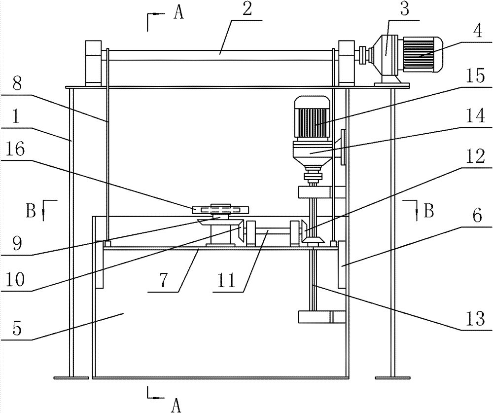
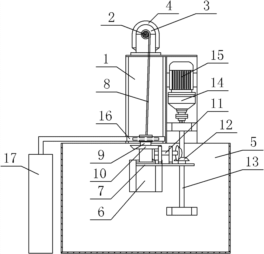
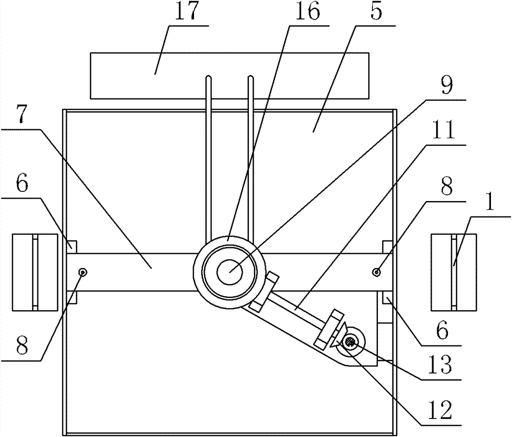
[0013] Such as Figure 1~3 As shown, the present invention includes a support 1, a horizontal shaft 2 is fixed on the top of the support 1 through a bearing seat, and one end of the horizontal shaft 2 is connected to the lifting motor 4 through a lifting reducer 3; The box 5 is provided with two chute 6 symmetrically on both sides inside the cooling box 5, and the two ends of the support plate 7 are stuck in the two chute 6, and the lower end of the steel wire rope 8 wound on the horizontal shaft 2 is fixedly connected with the support plate 7. A sprocket shaft 9 is vertically arranged on the support plate 7, and the sprocket shaft 9 is connected to one end of the intermediate shaft 11 which is horizontally arranged on the support plate 7 through the bear...


PUM


Abstract

The invention relates to a quenching device for a tooth surface of a chain wheel, and the quenching device comprises a support, wherein a horizontal shaft is fixed on the top of the support through a bearing seat, and one end of the horizontal shaft is connected with an elevation motor through an elevation speed reducer; a cooling box with an opened top part is arranged below the support, two sliding chutes are symmetrically formed on both sides inside the cooling box, two ends of the a support plate are clamped in the two sliding chutes, the lower end of a steel rope wrapped around the horizontal shaft is fixedly connected with the support plate, a chain wheel shaft is vertically arranged on the supporting plate, the chain wheel shaft is connected with one end of an intermediate shaft through a first conical gear set, the other end of the intermediate shaft is connected with the vertical shaft of a key groove through a second conical gear set, and the upper end of the vertical shaft of the key groove is connected with a chain wheel rotation motor through a chain wheel rotation speed reducer; and a heating ring is arranged at the upper part, corresponding to the chain wheel shaft,of the cooling box, and the heating ring is connected with a heating device arranged at one side of the cooling box. The quenching device provided by the invention is convenient to use, has short production process, and can be used for reducing the labor intensity, saving time and labor, ensuring the quenching quality and increasing the production efficiency.

Description

Technical field: [0001] The invention relates to a quenching device, in particular to a sprocket tooth surface quenching device. Background technique: [0002] At present, most of the sprocket tooth surface quenching is divided into two steps of heating and cooling. First, the sprocket tooth surface is heated. After the heating is completed, the operator manually moves the sprocket to the cooling pool to cool it. The entire production The process takes a long time and is time-consuming and laborious. Moreover, during the process of moving to the cooling pool after heating, the tooth surface of the sprocket is easily oxidized, the quenching efficiency is poor, the quality is difficult to guarantee, and the entire production efficiency is low. Invention content: [0003] The invention provides a sprocket tooth surface quenching device, which is simple in structure, convenient to use, short in production process, reduces the labor intensity of workers, saves time and effort, ...

Claims


Application Information

Patent Timeline
Patent Type & Authority Patents(China)
IPC IPC(8): C21D1/62C21D9/32C21D1/10
CPCY02P10/25
Inventor 张来斌王瑞国李长春李计良宋庆安
Owner 山东开泰工业科技有限公司
Why Eureka
Try Eureka