Enhanced type shrinkage-compensating ultrahigh-performance concrete hollow plate hinge joint structure

An ultra-high-performance, shrinkage-compensating technology, applied to bridge parts, bridges, buildings, etc., can solve problems such as bending resistance and shear bearing capacity deviation, achieve high connection strength, good mechanical performance, and avoid shrinkage cracking.

Pending Publication Date: 2018-05-18
HUNAN UNIV
View PDF1 Cites 2 Cited by
  • Summary
  • Abstract
  • Description
  • Claims
  • Application Information

AI Technical Summary

Problems solved by technology

The bending and shear bearing capacity deviation of the hollow slab girder bridge structure

Method used


Image

  • Enhanced type shrinkage-compensating ultrahigh-performance concrete hollow plate hinge joint structure
  • Enhanced type shrinkage-compensating ultrahigh-performance concrete hollow plate hinge joint structure
  • Enhanced type shrinkage-compensating ultrahigh-performance concrete hollow plate hinge joint structure

Examples


Embodiment 1

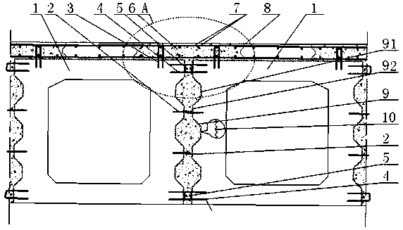
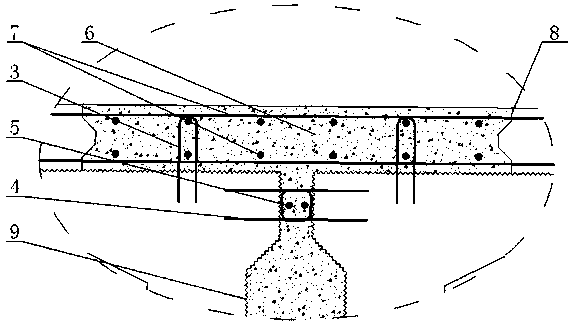
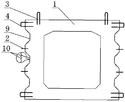
[0031] refer to Figure 1~2 : The reinforced shrinkage-compensated ultra-high-performance concrete hollow slab hinged joint structure of the present embodiment includes web annular anchor bars 4 and plate top annular anchor bars 3 distributed on the outer sides of the webs of two adjacent concrete hollow slabs 1 at the upper and lower ends , seam top steel bar 11 mesh 7, key tooth anchor bar 2 and longitudinal steel bar 5, and the shrinkage-compensating ultra-high-performance concrete 6 cast in the hinge joint of adjacent concrete hollow slabs; the top of the concrete hollow slab 1 is provided with a seam top Steel bars 11 mesh 7 and slab top annular anchor bars 3, slab top annular anchor bars 3 are located on both sides of the hinge joint, and are connected with the seam top steel bars 11 mesh 7; the outer surface of the web of the concrete hollow slab 1 is provided with key teeth 9. The key tooth anchor bar 2 is embedded in the concrete hollow plate 1 located at the protrusi...

Embodiment 2

[0042] refer to Figure 4~5 : Compared with Embodiment 1, the reinforced shrinkage-compensated ultra-high-performance concrete hollow slab hinged joint structure of the present embodiment has the following differences:

[0043] The shrinkage-compensating ultra-high-performance concrete 6 is ultra-high-performance concrete with an expansion agent added, and the expansion agent is UEA expansion agent, and its addition amount is 8% W / W of the ultra-high-performance concrete cementitious material, and the ultra-high performance The glue ratio of concrete is 0.18.

[0044] The hinged joint structure also includes a seam top anchor bar 11, which is embedded in the hinge joint of the adjacent concrete hollow slab 1, and the lower end of the seam top anchor bar 11 is handed over to the web annular anchor bar 4, Its upper end is handed over with seam top reinforcing bar 11 mesh 7.

[0045] The construction method of the hinged joint structure comprises the following steps:

[0046] ...


PUM


Abstract

An enhanced type shrinkage-compensating ultrahigh-performance concrete hollow plate hinge joint structure comprises web annular anchor bars, plate top annular anchor bars, joint top steel bar meshes,key tooth anchor bars and longitudinal steel bars which are distributed at the upper end and the lower end of the outer side face of webs of two adjacent concrete hollow plates and further comprises shrinkage-compensating ultrahigh-performance concrete poured into a hinge joint of the adjacent concrete hollow plates. The joint top steel bar meshes and the plate top annular anchor bars are arrangedon the tops of the concrete hollow plates, the plate top annular anchor bars are located on the two sides of the hinge joint and connected with the joint top steel bar meshes; key teeth are arrangedon the outer side faces of the webs of the concrete hollow plates, and the key tooth anchor bars are embedded in the positions, located in the protruding positions of the key teeth, of the concrete hollow plates; and the adjacent web annular anchor bars are connected in a lapping mode, and the longitudinal steel bars are arranged in the overlapped positions formed by lapping connection of the adjacent web annular anchor bars. The hinge joint structure is high in connecting strength, good in stress performance, high in durability, easy and convenient to construct and good in economic benefit.

Description

technical field [0001] The invention relates to a bridge reinforcement technology, in particular to a reinforced shrinkage-compensating ultra-high-performance concrete hollow slab hinged joint structure. Background technique [0002] With the rapid increase of traffic volume and overloaded vehicles, coupled with the influence of the natural environment, the hinge joints of a large number of concrete hollow slab bridges in service are generally damaged to varying degrees, mainly manifested as bridge deck pavement along the hollow slab hinge joints. Longitudinal cracking, water leakage, hinged concrete cracking and falling off, etc. After the hinge joint is damaged, it will cause the "single plate stress" of the hollow slab, which makes the upper main load-bearing components in a very unfavorable stress state, driving comfort, bridge safety and durability are significantly reduced, and a large amount of maintenance funds have to be spent every year It is used for reinforcemen...

Claims


Application Information

Patent Timeline
Patent Type & Authority Applications(China)
IPC IPC(8): E01D19/06
CPCE01D19/067
Inventor 张阳阳晴廖新辉陈贝施建群霍书亚方震
Owner HUNAN UNIV
Why Eureka
Try Eureka