Intermediate-frequency furnace bottom waste purifying smelting device and operation method

An intermediate frequency furnace, intermediate frequency technology, applied in the direction of furnace, crucible furnace, furnace type, etc., can solve the problems of furnace bottom cracking, high temperature duration, no cooling measures, etc., to achieve the effect of protecting electrical valves and furnace bottom

Inactive Publication Date: 2018-05-18
民乐县锦世建材新材料有限责任公司
View PDF7 Cites 0 Cited by
  • Summary
  • Abstract
  • Description
  • Claims
  • Application Information

AI Technical Summary

Problems solved by technology

[0002] As we all know, the intermediate frequency furnace is a melting furnace that uses the principle of electromagnetic induction to heat the metal placed in its own furnace cavity. The conventional intermediate frequency furnace generally includes a furnace body assembly and a furnace bottom located at the lower part of the furnace body assembly. The furnace bottom is composed of multiple refractory In the process of smelting metal, the working conditions of the bottom of the furnace are generally very harsh. It usually has to withstand a high temperature of more than 1600 degrees Celsius, and the high temperature lasts for a long time. After the metal is smelted, this high temperature will drop sharply. , when the metal is smelted next time, the bottom of the furnace will be repeatedly subjected to this process of high temperature and rapid temperature drop.
[0003] The existing intermediate frequency furnace bottom smelting device does not have a waste purification device, does not do a good job of cleaning up after smelting, and does not have good cooling measures at the same time, which may easily lead to cracking of the furnace bottom

Method used


Image

  • Intermediate-frequency furnace bottom waste purifying smelting device and operation method
  • Intermediate-frequency furnace bottom waste purifying smelting device and operation method
  • Intermediate-frequency furnace bottom waste purifying smelting device and operation method

Examples


Embodiment Construction

[0013] The following will clearly and completely describe the technical solutions in the embodiments of the present invention with reference to the accompanying drawings in the embodiments of the present invention. Obviously, the described embodiments are only some, not all, embodiments of the present invention. Based on the embodiments of the present invention, all other embodiments obtained by persons of ordinary skill in the art without making creative efforts belong to the protection scope of the present invention.

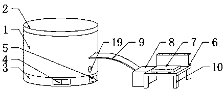
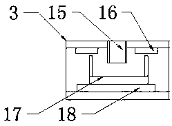
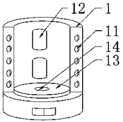
[0014] see Figure 1-4 , the present invention provides a technical solution: an intermediate frequency furnace bottom waste purification and smelting device, including a purification and smelting device body 1, an operation table 6 and an electric control box 8, the electric control box 8 is welded to one side of the operation table 6, and the purification and smelting device The top of the body 1 is provided with an upper top cover 2, and the upper top cover...


PUM


Abstract

The invention relates to the technical field of purifying smelting devices, in particular to an intermediate-frequency furnace bottom waste purifying smelting device and an operation method. The intermediate-frequency furnace bottom waste purifying smelting device comprises a purifying smelting device body, an operation table and an electric control box; and the electric control box is welded to one side of the operation table, and an upper top cover is arranged on the top of the purifying smelting device body, arranged in the purifying smelting device body in an embedded mode and movably connected with the purifying smelting device body through threads. According to the intermediate-frequency furnace bottom waste purifying smelting device, an electrical valve is mounted in the middle position of the smelting furnace bottom, the top of the electrical valve is formed by splicing of a plurality of refractor bricks, the role of protecting of the electrical valve is realized, meanwhile, smelted waste can flow from a guiding tube at the bottom of the electrical valve into a collecting vessel, and then the collecting vessel is taken out by opening a double door; and meanwhile, a coolingpipe is further arranged in the purifying smelting device body, in this way, a suitable temperature for cooling can be ensured, cracking of the furnace bottom does not occur, and the furnace bottom isprotected.

Description

technical field [0001] The invention relates to the technical field of purification and smelting devices, in particular to an intermediate frequency furnace bottom waste purification and smelting device and an operation method. Background technique [0002] As we all know, the intermediate frequency furnace is a melting furnace that uses the principle of electromagnetic induction to heat the metal placed in its own furnace cavity. The conventional intermediate frequency furnace generally includes a furnace body assembly and a furnace bottom located at the lower part of the furnace body assembly. The furnace bottom is composed of multiple refractory In the process of smelting metal, the working conditions of the bottom of the furnace are generally very harsh. It usually has to withstand high temperatures above 1600 degrees Celsius, and the high temperature lasts for a long time. After the metal is smelted, this high temperature will drop sharply. , when the metal is smelted n...

Claims


Application Information

Patent Timeline
Patent Type & Authority Applications(China)
IPC IPC(8): F27B14/06F27B14/18F27B14/14F27B14/20F27B14/08
Inventor 何喜善李毓虎章禄林
Owner 民乐县锦世建材新材料有限责任公司
Why Eureka
Try Eureka