
Indoor noise source localization method based on spherical surface near-field acoustic holography reconstructing reactive sound intensity

A near-field acoustic holography, indoor noise technology, applied in radio wave measurement systems, using re-radiation, measurement devices and other directions, can solve the problem of not being able to determine the location of the noise source, and achieve the effect of eliminating the influence of indoor reverberation environment and effective positioning. Effect

Active Publication Date: 2018-05-18
GUIZHOU AEROSPACE INST OF MEASURING & TESTING TECH
View PDF14 Cites 9 Cited by
  • Summary
  • Abstract
  • Description
  • Claims
  • Application Information

AI Technical Summary

Problems solved by technology

However, in internal spaces such as small rooms, due to the reflection of the ceiling and walls, the internal sound field will produce multiple strong modes superimposed into a reverberation field. At this time, the near-field acoustic holographic algorithm suitable for free field reconstruction of the sound source Sound pressure on nearby surfaces often does not determine noise source location

Method used


Image

  • Indoor noise source localization method based on spherical surface near-field acoustic holography reconstructing reactive sound intensity
  • Indoor noise source localization method based on spherical surface near-field acoustic holography reconstructing reactive sound intensity
  • Indoor noise source localization method based on spherical surface near-field acoustic holography reconstructing reactive sound intensity

Examples


Embodiment Construction

[0053] Below in conjunction with accompanying drawing and specific embodiment the invention is further introduced:

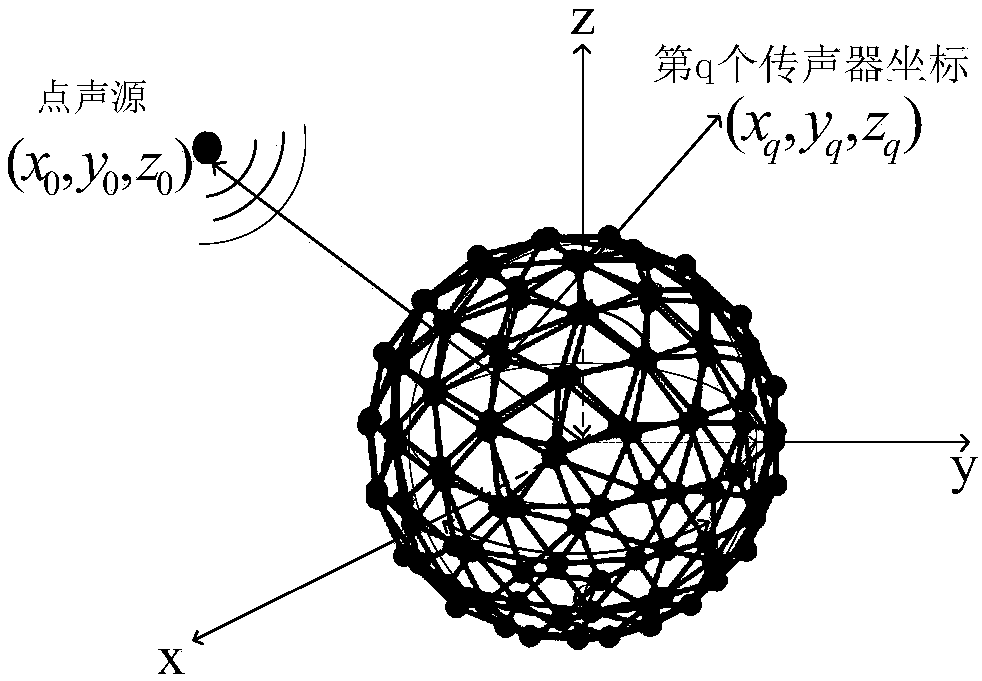
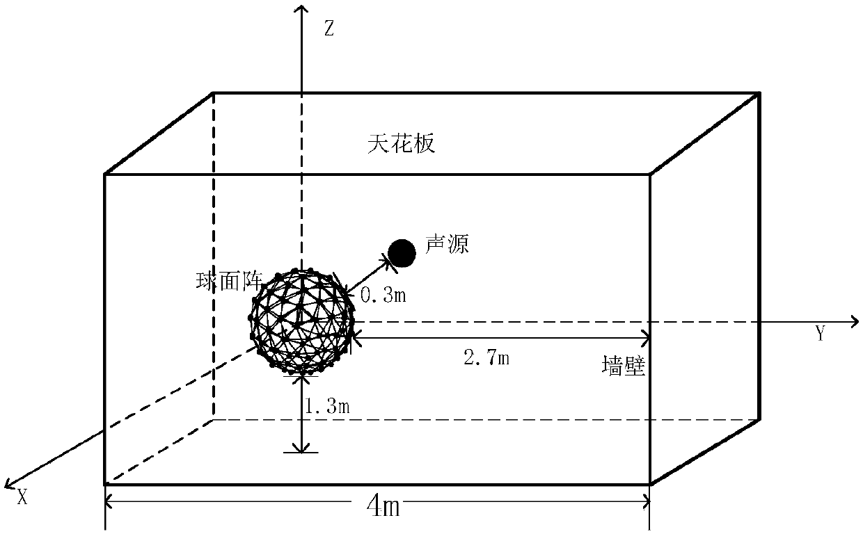
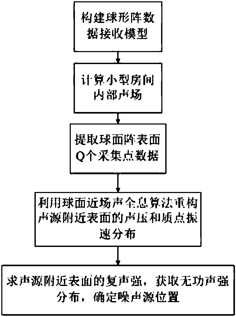
[0054] Process flow of the present invention such as image 3 As shown, first calculate the radiated sound field of the sound source in a room of a given size, extract the data of the collection points of the spherical array, perform cross-spectrum analysis on the data of the Q channels and the data of the first channel, and obtain the complex sound pressure in the frequency domain of the spherical array , using the spherical near-field acoustic holographic algorithm to reconstruct the sound pressure distribution and the particle velocity distribution on the surface near the sound source, the complex sound intensity of the surface near the sound source is obtained through the complex sound intensity calculation formula, and its imaginary part is extracted as its reactive part, Use the reactive sound intensity distribution on the surface near the sound source to ...


PUM


Abstract

The invention discloses an indoor noise source localization method based on spherical surface near-field acoustic holography reconstructing reactive sound intensity. The method comprises the followingsteps: (1) calculating a three-dimensional spatial sound field data radiated by a mechanical sound source inside a regular small room; (2) using a spherical microphone array with Q array elements toacquire a sound pressure signal radiated from the target sound source to the three-dimensional space; (3) subjecting the Q pieces of microphone data of the spherical array and the first microphone data to cross spectrum analysis separately to obtain the frequency-domain complex sound pressure of the entire spherical array; (4) using a spherical near-field acoustic holographic algorithm to reconstruct the sound pressure and the mass point vibration velocity of the sound source surface; and (5) using the complex sound pressure and the mass point vibration velocity to reconstruct the surface complex sound intensity near the sound source to extract the reactive sound intensity; and determining the location of the indoor noise source by the reactive sound intensity distribution. Compared with the prior art, the method utilizes a fact that the reactive sound intensity is powerful in the near-field region of the sound source to eliminate the influence of indoor reverberation environment and effectively locate the indoor noise source.

Description

technical field [0001] The invention relates to a method for locating an indoor noise source, in particular to a method for locating an indoor noise source by using a spherical near-field acoustic holographic algorithm to reconstruct the distribution of reactive sound intensity on a surface near a sound source. Background technique [0002] Excessive noise inside a small room will endanger the health of the staff. Therefore, it is very important to effectively control the indoor noise source. The necessary prerequisite for effective control of the noise source is to accurately locate the noise source. [0003] In the field of noise source localization, sound field measurement using a microphone array is the most commonly used method. More commonly used are planar microphone arrays, but the limitation of planar arrays is that they cannot distinguish between sounds in front of or behind the array. Due to the reflection of the wall and ceiling in a small room, the internal sou...

Claims


Application Information

Patent Timeline
IPC IPC(8): G01S11/14
CPCG01S11/14
Inventor 丁丹丹张睿朱永晓陈伟
Owner GUIZHOU AEROSPACE INST OF MEASURING & TESTING TECH
Learn More