Large-field-of-view super-resolution dynamic phase non-lens micro-imaging device and reconstruction method
A lensless microscopy and super-resolution technology, applied in microscopes, instruments, optics, etc., can solve the problems of limited intensity super-resolution, inability to collect, increase system cost, etc., to solve problems that are difficult to take into account at the same time, and reduce calibration accuracy The effect of improving the robustness
- Summary
- Abstract
- Description
- Claims
- Application Information
AI Technical Summary
Problems solved by technology
Method used
Image

Examples
Embodiment Construction
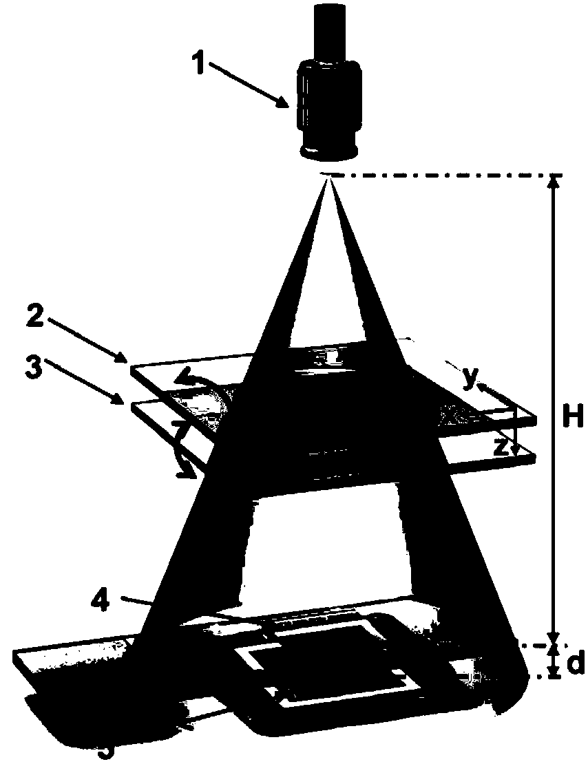
[0019] In the lensless microscopic imaging device for super-resolution dynamic phase of the present invention, the imaging system is composed of a partially coherent or coherent light source 1, a first parallel plate 2, a second parallel plate 3, a sample stage 4, and an imaging sensor 5. The light source 1 is used as the illumination light source of the lensless microscope, which is placed directly above the sample stage 4, and the luminescent center of the light source is located on the optical axis of the entire imaging system.
[0020] The distance H between the partially coherent or coherent light source 1 and the upper surface of the sample 4 is generally 20-40 mm, and the distance d between the camera 5 and the sample 4 is 5 μm-2 mm. The first parallel plate 2 and the second parallel plate 3 are composed of two pieces of glass, and are placed between the partially coherent or coherent light source 1 and the sample stage 4 .
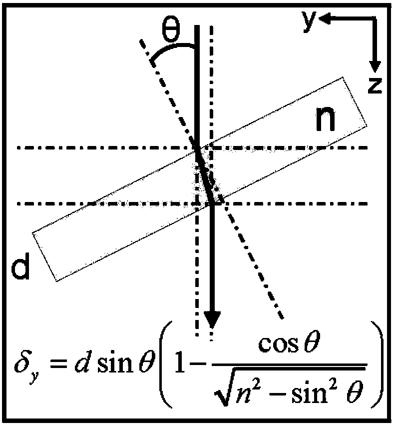
[0021] Since the refractive index of the par...
PUM
 Abstract
Description
Claims
Application Information
 - Generate Ideas
- Intellectual Property
- Life Sciences
- Materials
- Tech Scout
- Unparalleled Data Quality
- Higher Quality Content
- 60% Fewer Hallucinations
Browse by: Latest US Patents, China's latest patents, Technical Efficacy Thesaurus, Application Domain, Technology Topic, Popular Technical Reports.
© 2025 PatSnap. All rights reserved.Legal|Privacy policy|Modern Slavery Act Transparency Statement|Sitemap|About US| Contact US: help@patsnap.com