Wire tensioning device

A tensioning device and wire technology, which is applied in the field of wire tensioning devices and transposition wire equipment, can solve the problems of affecting the processing of transposition process, the effect of tension is not obvious, and the wires are prone to jumping wires, etc., and achieve the effect of simple overall structure

Inactive Publication Date: 2018-05-18
马西刚
View PDF0 Cites 2 Cited by
  • Summary
  • Abstract
  • Description
  • Claims
  • Application Information

AI Technical Summary

Problems solved by technology

[0003] Before the transposition process of the production transposition wire, it is necessary to control the tension of the wire pay-off. The traditional method is to install a tension device on the pay-off cradle, and use the friction damping method to control the tension of the friction of the brake disc through the brake belt. However, the actual In general, the tension control effect of this kind of passive control is not obvious, and because there is a certain distance between the winch and the transposition machine, and the wire is still in a bent state due to the weight of the wire, it cannot be guaranteed that it is always in a tensioned state, which affects the transposition The processing of the process makes the wires prone to wire jumping

Method used


Image

  • Wire tensioning device

Examples


Embodiment Construction

[0013] The present invention will be further described below in conjunction with the drawings.

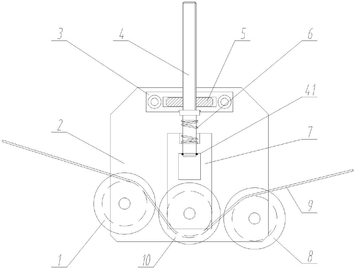
[0014] Such as figure 1 As shown, this wire tensioning device includes a fixed plate 2, a left roller 1, a middle roller 10, a right roller 8 and a central shaft 4;

[0015] The left roller 1 is rotatably mounted on the left front end of the fixed plate 2, the right roller 8 is rotatably mounted on the right front end of the fixed plate 2, and the middle roller 10 is mounted on the connecting block 7 and located at the middle front end of the fixed plate 2. The lower part of the central shaft 4 is slidably mounted on the connecting block 7 up and down, and the lower end is provided with a limit ring 41. The lower part of the central shaft 4 is sleeved with an elastic device 6 whose one end is in contact with the middle of the central shaft 4 and the other end Contact with the upper end of the connecting block 7;

[0016] The upper part of the central shaft 4 has a threaded structure and...


PUM


Abstract

The invention discloses a wire tensioning device. The device comprises a fixing plate, a left idler wheel, a middle idler wheel, a right idler wheel and a center shaft; the left idler wheel is rotatably arranged at the front end of the left side of the fixing plate, the right idler wheel is rotatably arranged at the front end of the right side of the fixing plate, and the middle idler wheel is arranged on a connection block and located at the front end of the middle of the fixing plate; the lower portion of the center shaft is up and down slidingly arranged on the connection block, a limit ring is arranged at the lower end of the center shaft, the lower portion of the center shaft is sleeved with an elastic device, one end of the elastic device is in contact with the middle of the center shaft, and the other end of the elastic device is in contact with the upper end of the connection block; the upper portion of the center shaft is of a threaded structure and penetrates through a top plate, an adjustment block is matched with the upper portion of the center shaft through a screw thread and located in a through hole in the middle of the top plate, and the top plate is fixedly arranged at the upper end of the fixing plate; the upper ends of the left idler wheel and the right idler wheel are in contact with the lower surface of a wire, and the lower end of the middle idler wheel isin contact with the upper surface of the wire. The wire tensioning device is simple in structure, automatic wire tensioning can be achieved, and the constant tension of the wire is kept.

Description

Technical field [0001] The invention relates to a tensioning device, in particular to a wire tensioning device, belonging to transposition wire equipment. Background technique [0002] Transposed wire refers to a certain number of enameled copper flat wires, overlapped in the width direction and divided into two rows, and the two wires in the upper and lower positions are transposed by the same direction from beginning to end, and electrician Insulating paper tape is used as a winding wire formed by multi-layer continuous tightly wrapped windings. [0003] Before the transposition process of producing transposition wires, the wire pay-off tension needs to be controlled. The traditional method is to install a tension device on the wire pay-off cradle, and use the friction damping method to control the friction of the brake disc through the brake band. Above, this kind of passive tension control effect is not obvious, and because there is a certain distance between the winch and the...

Claims


Application Information

Patent Timeline
Patent Type & Authority Applications(China)
IPC IPC(8): H01F41/094
CPCH01F41/094
Inventor 马西刚
Owner 马西刚
Why Eureka
Try Eureka