High voltage connector used for testing ultra-high voltage traveling-wave tube

A high-voltage connector, traveling wave tube technology, applied in the direction of contact parts, fixed/insulated contact members, etc., can solve problems such as economic loss, damage to traveling wave tubes and test equipment and instruments

Inactive Publication Date: 2018-05-18
WUHU BLUE SKY ENG PLASTIC CO LTD
View PDF7 Cites 0 Cited by
  • Summary
  • Abstract
  • Description
  • Claims
  • Application Information

AI Technical Summary

Problems solved by technology

[0004] In view of the above-mentioned prior art, the purpose of the present invention is to overcome the high-voltage connector ignition caused by creeping fire on the surface contacted by the male and female joints of the high-voltage connector when testing the traveling wave tube in the prior art, thus causing the traveling wave tube to burn. The problem of damage to test equipment and instruments, resulting in significant economic losses, thus designing a new high-voltage connector for ultra-high-voltage traveling wave tube testing that matches the high-voltage connector that comes with the traveling wave tube to reduce The problem of creeping fire on the surface contacted by the female connector

Method used


Image

  • High voltage connector used for testing ultra-high voltage traveling-wave tube
  • High voltage connector used for testing ultra-high voltage traveling-wave tube
  • High voltage connector used for testing ultra-high voltage traveling-wave tube

Examples


Embodiment Construction

[0029] Specific embodiments of the present invention will be described in detail below in conjunction with the accompanying drawings. It should be understood that the specific embodiments described here are only used to illustrate and explain the present invention, and are not intended to limit the present invention.

[0030] In the present invention, in the absence of a contrary statement, the orientation words included in the term, such as "upper, lower, inner, outer", etc., only represent the orientation of the term in the normal use state, or are understood by those skilled in the art. colloquial term and should not be construed as a limitation of the term.

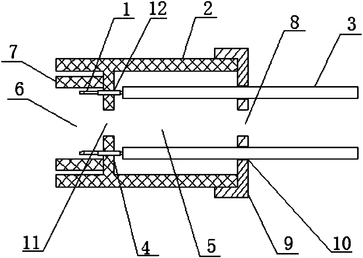
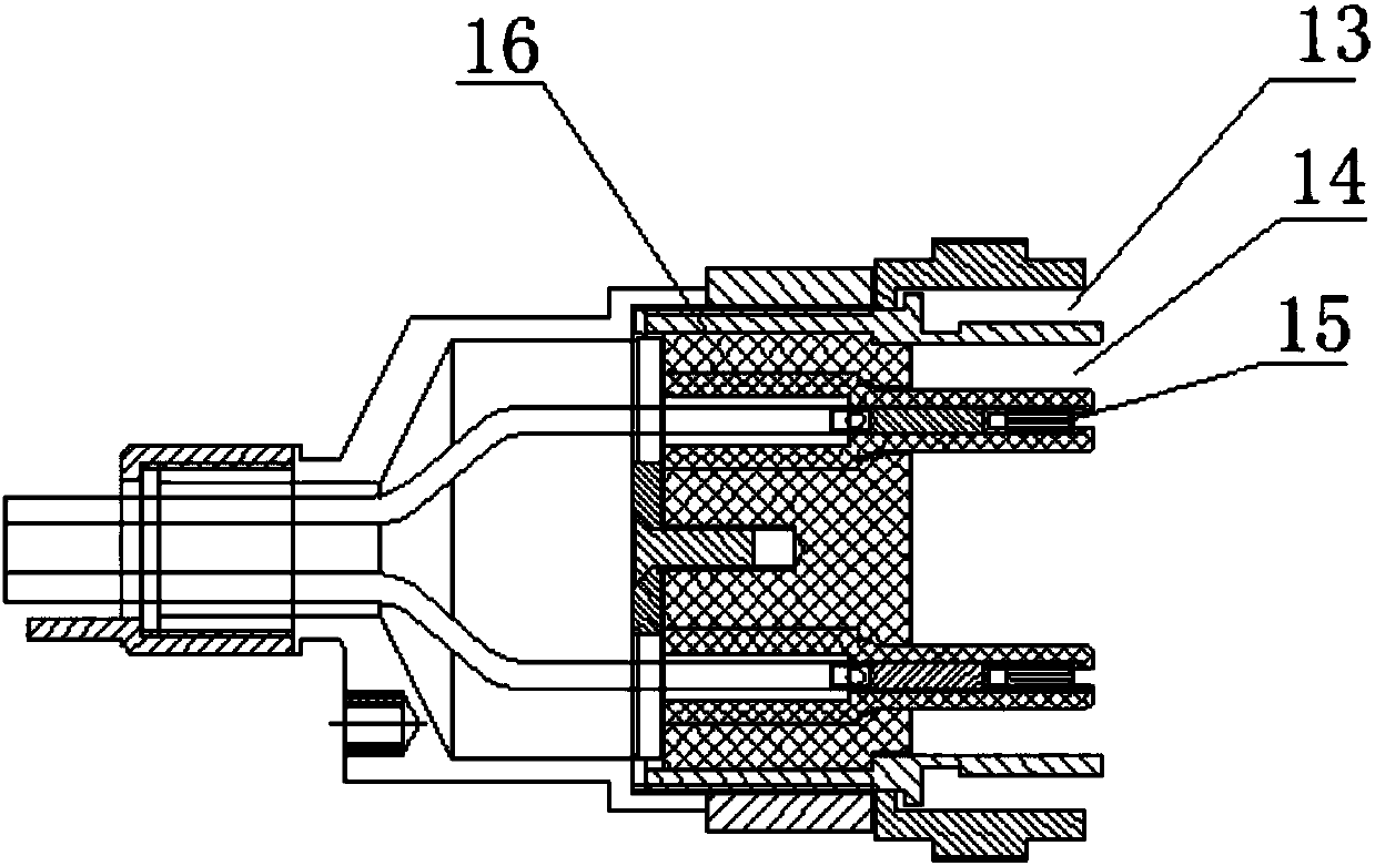
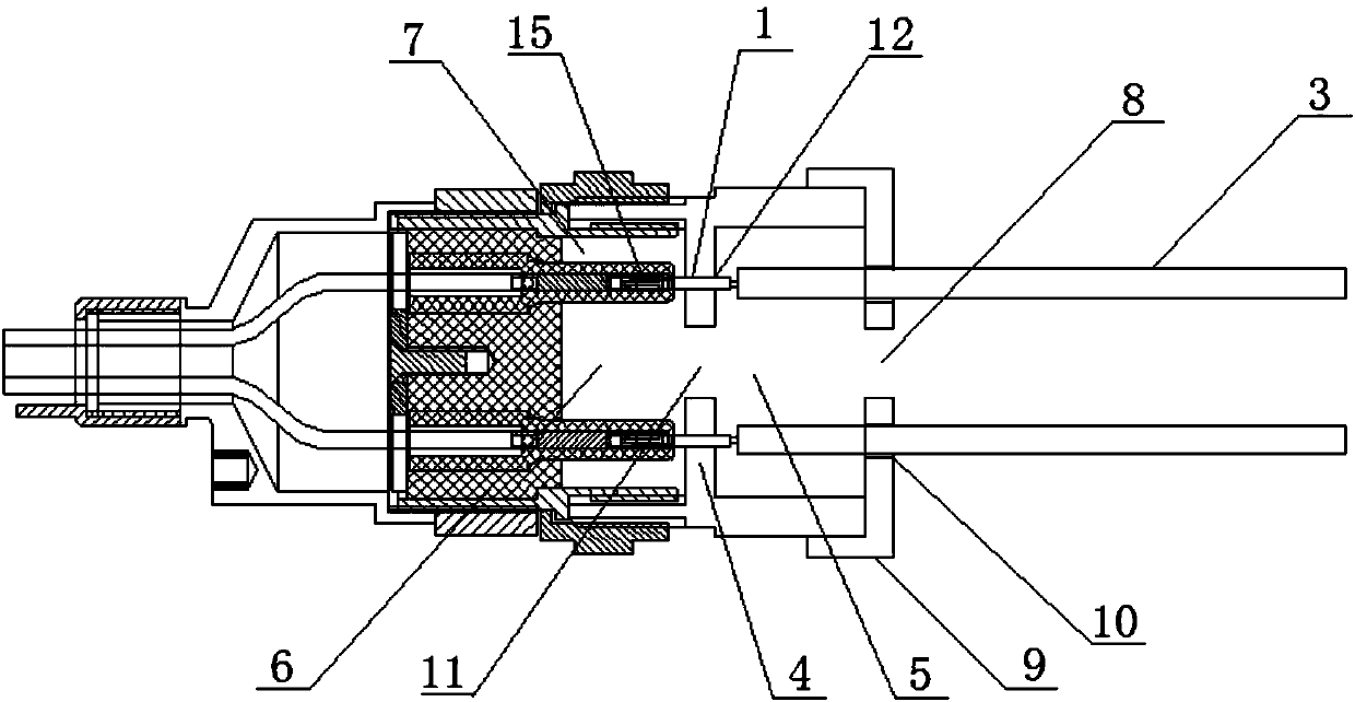
[0031] Such as Figure 1-4 As shown, the present invention provides a high-voltage connector for ultra-high voltage traveling wave tube testing. The high-voltage connector for ultra-high voltage traveling wave tube testing includes: a cylinder 2, a wire connecting pin 1, a high-voltage wire 3, a cover 9 and The inte...


PUM


Abstract

The present invention discloses a high voltage connector used for testing an ultra-high voltage traveling-wave tube. The connector comprises a cylinder, wire connection needles, high-voltage wires, alid and an interlayer. The inside of the cylinder is provided with a penetrating cavity along the center line of the cylinder, the interlayer is perpendicularly arranged in the cylinder, and thus thecavity is divided into a first cavity and a second cavity. The interlayer is provided with multiple first through holes, the wire connection needles are fixed in the first through holes, and both endsof each wire connection needle stretch out of the corresponding first through hole. One end of each high-voltage wire is connected with the end, turning towards the first cavity, of the correspondingwire connection needle. The lid is covered and fixed on the end, near the first cavity, of the cylinder, and the lid is provided with multiple second through holes matched with the high-voltage wires. According to the high voltage connector, the existing problems in the conventional technology are overcome, for example, in the conventional technology, when the traveling-wave tube is tested, the surface of the contacting of a male connector and a female connector of the high voltage connector creeps fire to cause the high voltage connector to strike fire, so that the traveling-wave tube, testing equipments and testing instruments are damaged, and thus significant economic losses are brought.

Description

technical field [0001] The invention relates to a high-voltage connector for testing a traveling wave tube, in particular to a high-voltage connector for testing an ultrahigh-voltage traveling wave tube. Background technique [0002] Traveling wave tubes are increasingly playing an irreplaceable role in modern satellite communications and satellite navigation, especially in military electronic equipment such as electronic jamming equipment, early warning aircraft, fire control radar, and precision guidance. Traveling wave tubes usually work under high pressure. When testing traveling wave tubes, ignition of high-voltage connectors may cause damage to traveling wave tubes and test equipment, resulting in significant economic losses. The main reason for the ignition of high-voltage connectors is that the surface contacted by the male and female connectors of the high-voltage connectors climbs fire. [0003] In order to reduce the surface creepage caused by the contact between...

Claims


Application Information

Patent Timeline
Patent Type & Authority Applications(China)
IPC IPC(8): H01R13/40H01R13/03
CPCH01R13/40H01R13/03
Inventor 钱万水
Owner WUHU BLUE SKY ENG PLASTIC CO LTD
Why Eureka
Try Eureka