a lumbar seat
A lumbar support and seat technology, which is applied to chairs, other seating furniture, stools, etc., can solve the problems of lumbar support telescopic adjustment, unsatisfactory lumbar support use effect, and loose lumbar support, so as to increase comfort. , Improve the aesthetics, the support force is even and lasting
- Summary
- Abstract
- Description
- Claims
- Application Information
AI Technical Summary
Problems solved by technology
Method used
Image
Examples
Embodiment 1
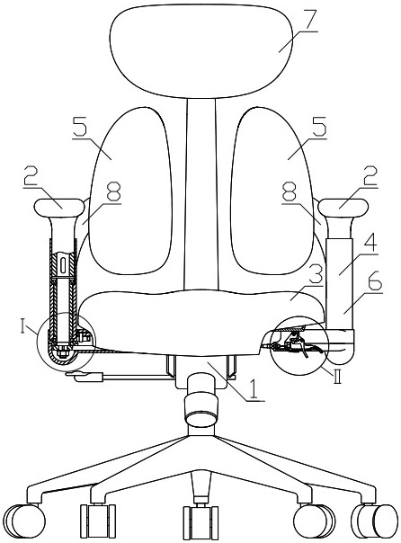
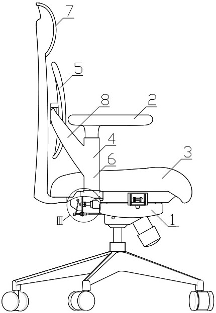
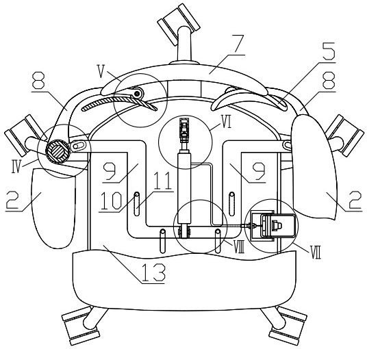
[0093] Example 1, such as figure 1 , figure 2 , image 3 , Figure 7 , Figure 8 , Figure 9 , Figure 10 , Figure 11 , Figure 12 , Figure 13 , Figure 14 The chair whose backrest can be moved close to the lower back of the human body as shown includes a chair foot assembly 1, a seat cushion 3, an armrest assembly 4 and a backrest 5. A rocker 8 is arranged on the upper part of the sleeve 6 of the armrest assembly 4, and the front end of the rocker arm 8 is The bottom of the seat cushion 3 is fixed with the bottom plate 13, and the bottom of the bottom plate 13 is fixedly connected with the top of the chair leg assembly 1, and the rear part of the bottom plate 13 is fixed with a control frame 31. Connected to the front of the air rod 12, the tail of the air rod 12 is provided with a connecting pin 33 connected to one end of the connecting arm 9, and the other end of the connecting arm 9 is provided with a swing pin 17 that is movably embedded in the swing groove 18...
Embodiment 2
[0102] Example 2, such as Figure 4 , Figure 5 , Image 6 , Figure 7 , Figure 8 , Figure 9 , Figure 10 , Figure 12 , Figure 13 , Figure 14 , Figure 15 As shown, including chair foot assembly 1, seat cushion 3, armrest assembly 4 and backrest 5, the sleeve pipe 6 top of armrest assembly 4 is provided with rocker 8, and the front end portion of rocker arm 8 is provided with revolving pin 32 and the rear of backrest 5. The lower part of the seat cushion 3 is fixed with the base plate 13, the lower part of the base plate 13 is fixedly connected with the upper part of the chair foot assembly 1, the fixed control frame 31 at the rear of the base plate 13 is connected with the front part of the air rod 12, and the air rod The afterbody of 12 is provided with connecting pin 33 and is connected with one end of connecting arm 9, and the other end of connecting arm 9 is provided with swinging pin 17 and movably inserts in the swinging groove 18 of sleeve pipe 6 bottoms....
Embodiment 3
[0113] The difference between Embodiment 3, Embodiment 4, Embodiment 5, Embodiment 6 and Embodiment 1 is mainly that the specific structure of the transmission part 40 is different.
[0114] Specifically, embodiment 3, such as Figure 16 with Figure 17 As shown, the gas spring 12 can be directly installed under the seat cushion 3, or can be indirectly assembled under the seat cushion 3 through a connecting part such as a bottom plate, and this technical solution is not limited. Achieving transmission through a rack and pinion is a form of realization of the transmission part 40. Specifically, the gas spring 12 is stretched to drive the connecting arm 41 forward, and the end of the connecting arm 41 is connected to the connecting rack 42, which drives the connecting rack 42. Pushing forward, the swing tooth 43 naturally rotates under the forward drive of the connecting rack 42, driving the swing of the lumbar support 5. The slotting direction of the long groove 11 is also th...
PUM
 Abstract
Description
Claims
Application Information
 - R&D
- Intellectual Property
- Life Sciences
- Materials
- Tech Scout
- Unparalleled Data Quality
- Higher Quality Content
- 60% Fewer Hallucinations
Browse by: Latest US Patents, China's latest patents, Technical Efficacy Thesaurus, Application Domain, Technology Topic, Popular Technical Reports.
© 2025 PatSnap. All rights reserved.Legal|Privacy policy|Modern Slavery Act Transparency Statement|Sitemap|About US| Contact US: help@patsnap.com


