Novel rubber tube wire cleaning device

A technology for cleaning devices and rubber hoses, which is applied in the direction of drying gas arrangement, cleaning methods and appliances, and cleaning methods using liquids, etc. It can solve problems affecting normal work and service life, etc., and achieve enhanced drying effect, accelerated evaporation, and expanded flushing range Effect

Inactive Publication Date: 2018-05-22
张家港市华鸿金属制品有限公司
View PDF5 Cites 6 Cited by
  • Summary
  • Abstract
  • Description
  • Claims
  • Application Information

AI Technical Summary

Problems solved by technology

During the production and processing of rubber hose steel wire, it needs to be hot-dip galvanized. By immersing the derusted rubber hose steel wire in a zinc solution at about 500 ° C, a layer of zinc layer is attached to the surface of the steel wire, so as to prevent corrosion. The purpose of the rubber hose steel wire is to clean the steel wire after hot-dip galvanizing, and rinse the residual zinc liquid on the steel wire surface, but the rubber hose steel wire cleaning device in the prior art does not dry it after cleaning, so that the steel wire surface There are still traces of water, and the steel wire of the hose that has been in a humid environment for a long time is prone to oxidation, which will affect its normal work and service life

Method used


Image

  • Novel rubber tube wire cleaning device
  • Novel rubber tube wire cleaning device
  • Novel rubber tube wire cleaning device

Examples


Embodiment Construction

[0014] The following will clearly and completely describe the technical solutions in the embodiments of the present invention with reference to the accompanying drawings in the embodiments of the present invention. Obviously, the described embodiments are only some, not all, embodiments of the present invention. Based on the embodiments of the present invention, all other embodiments obtained by persons of ordinary skill in the art without making creative efforts belong to the protection scope of the present invention.

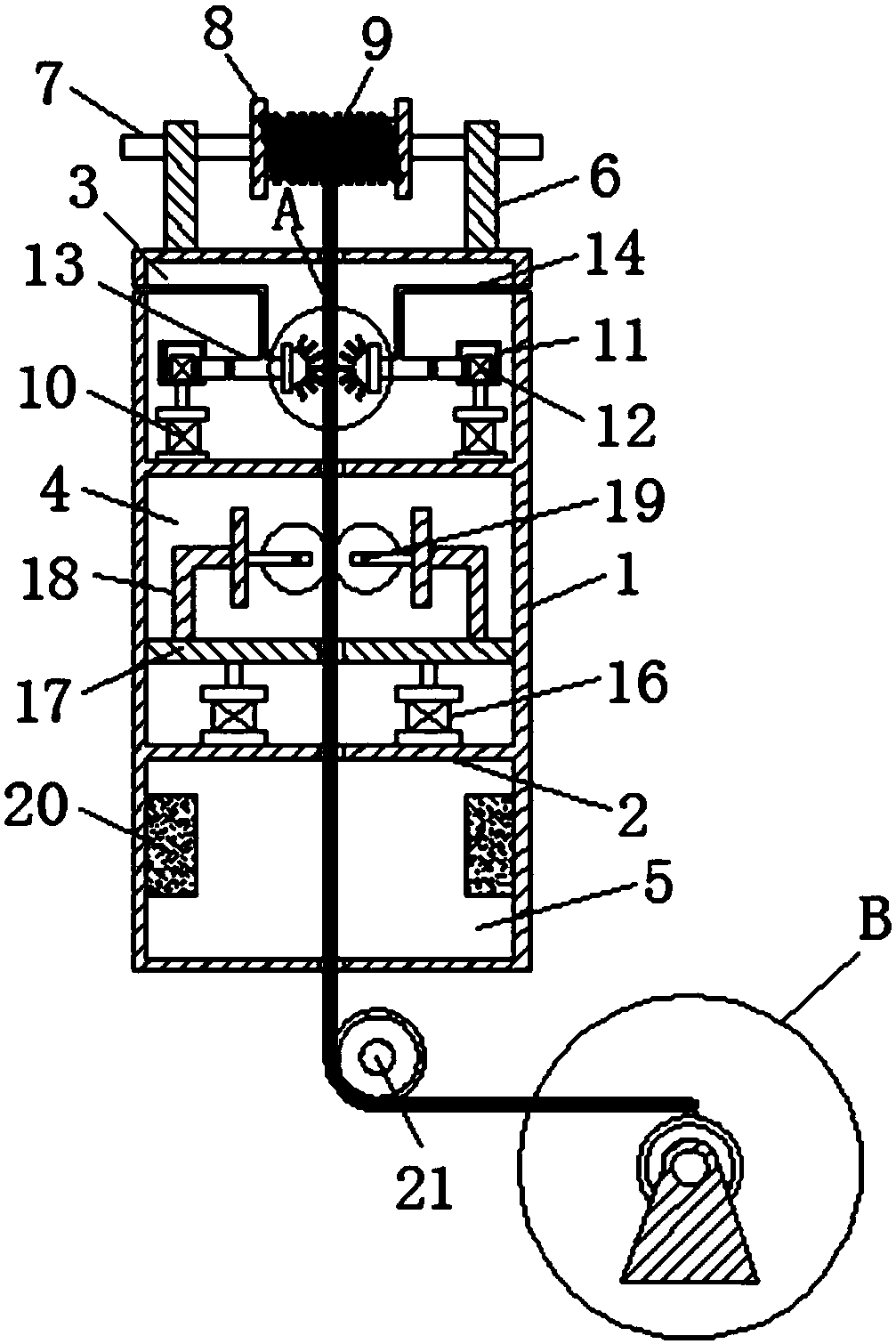
[0015] see Figure 1-3 , the present invention provides a technical solution: a new rubber hose steel wire cleaning device, including a housing 1, the inner cavity of the housing 1 is provided with two partitions 2, and the two ends of the partitions 2 are fixedly connected to the two ends of the housing 1. side inner wall, and two partitions 2 divide the inner cavity of the housing 1 into three parts: the washing chamber 3, the drying chamber 4 and the drying...


PUM


Abstract

The invention discloses a novel rubber tube wire cleaning device which comprises a shell. Partition plates are arranged in an inner cavity of the shell and further divide the inner cavity of the shellinto a washing bin, a drying bin and a roasting bin. The top ends of the two sides of the washing bin are fixedly connected with supports, and the supports are fixedly connected with a fixed shaft. The outer wall of the fixed shaft is movably connected with a spool. A rubber tube wire is wound onto the spool. First hydraulic cylinders are installed at the bottom ends of the two sides of the washing bin, and output shafts of the first hydraulic cylinders are fixedly connected with motor bins. Motors are installed in the corresponding motor bins. Output shafts of the motors are fixedly connected with washing pipes, and the outer walls of the washing pipes are fixedly connected with water inlet pipes. Washing sprayers are arranged at the bottom ends of the corresponding washing pipes. Secondhydraulic cylinders are installed at the bottom ends of the two sides of the drying bin. Output shafts of the second hydraulic cylinders are fixedly connected with a pushing plate, and the two sidesof the pushing plate are fixedly connected with mounting racks. The mounting racks are provided with drying rollers. Steam heaters are installed on the inner walls of the two sides of the roasting bin. A steering wheel is arranged below the shell, and a fixed base is arranged nearby the steering wheel. A take-up reel is installed on the fixed base.

Description

technical field [0001] The invention relates to the technical field of rubber hose steel wires, in particular to a novel rubber hose steel wire cleaning device. Background technique [0002] Hose is a type of tubular rubber product used to convey gas, liquid, slurry or granular materials. Hose manufacturing is an important part of the rubber industry. The hose structure is usually divided into inner rubber layer, outer rubber layer and skeleton layer. The skeleton layer, also known as the middle layer, is the pressure-bearing layer of the rubber hose, which endows the hose body with strength and hardness. The material of the skeleton layer can be cotton fiber, various synthetic fibers, carbon fiber or asbestos, steel wire, etc. During the production and processing of rubber hose steel wire, it needs to be hot-dip galvanized. By immersing the derusted rubber hose steel wire in a zinc liquid at about 500 ° C, a layer of zinc layer is attached to the surface of the steel wire,...

Claims


Application Information

Patent Timeline
Patent Type & Authority Applications(China)
IPC IPC(8): B08B3/02F26B13/04F26B13/14F26B13/26F26B13/28F26B21/00
CPCF26B13/14F26B13/26F26B13/28F26B21/005B08B3/022B08B3/024
Inventor 岳东钰
Owner 张家港市华鸿金属制品有限公司
Why Eureka
Try Eureka