
Liquid state silica gel sizing device

A shaping device and liquid silicone technology, applied in the field of mechanical processing molds, can solve problems such as poor control of dispensing volume, increased raw material usage, and difficulty in controlling dispensing dosage, so as to achieve clear structure and reduce the use of raw materials , Improve the effect of beautiful appearance

Inactive Publication Date: 2018-05-22
SYNERGY HANIL PRECISION POLYMER TECH CO LTD
View PDF0 Cites 2 Cited by
  • Summary
  • Abstract
  • Description
  • Claims
  • Application Information

AI Technical Summary

Problems solved by technology

[0002] The rapid development of modern industrialization has entered various fields. Whether it is heavy industry or scientific and technological enterprises, the requirements for products are getting higher and higher. Mold processing, as the finalization of products, plays a decisive role in product quality. These mold processing is not only used For mechanical parts, there are more and more mold molding processes for those soft materials. Liquid silicone is widely used in the injection molding of mobile phone protective cases. Mobile phone cases that use liquid injection molding will have high production efficiency and small size. Due to its technical advantages such as stable appearance, it is widely used. However, due to the design of the mold itself, the control of the dispensing amount is not particularly good. It is often difficult to control the dispensing amount during the injection operation, so it will make The use of raw materials increases, which increases the processing cost

Method used


Image

  • Liquid state silica gel sizing device
  • Liquid state silica gel sizing device
  • Liquid state silica gel sizing device

Examples


Embodiment Construction

[0027] The specific implementation manners of the present invention will be briefly described below in conjunction with the accompanying drawings.

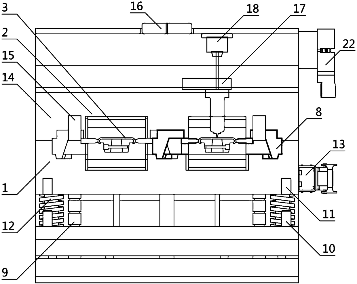
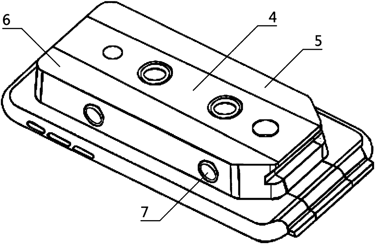
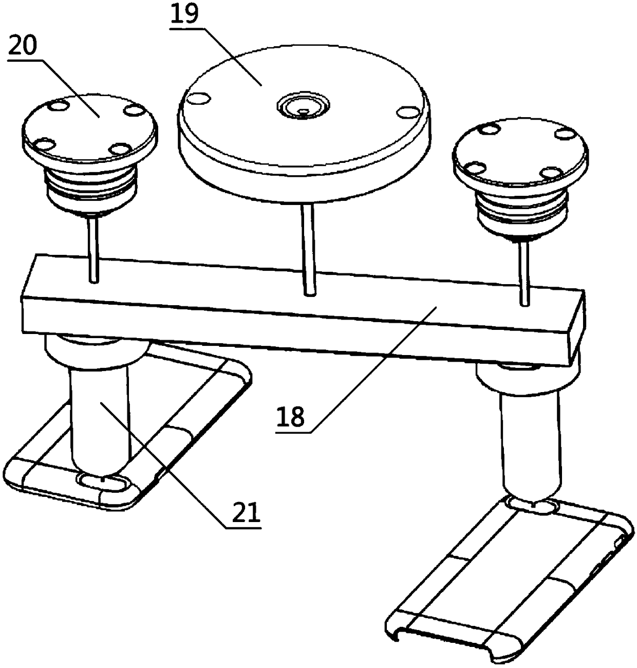
[0028] Such as figure 1 , figure 2 , image 3 , Figure 4A liquid silicone sizing device shown is characterized in that it consists of a lower template 1, several product implantation grooves 2, several product clamping blocks 8, a low-position glue release device 13, an upper template 14, a glue injection port 16, a cooling The runner dispensing device 17 and the high-position glue dispenser 22 are composed. Any of the product implantation grooves 2 is located in the middle of the lower template 1. The product implantation groove 2 is fixedly connected to the lower template 1. Any of the product implantation grooves The groove 2 is also provided with a product holder 3, the product holder 3 is located inside the product implantation groove 2, and the product holder 3 is fixedly connected with the product insertion groove 2, a...


PUM


Abstract

The invention aims to provide a liquid state silica gel sizing device. According to the technical scheme, the liquid state silica gel sizing device is composed of a lower mold plate, product implanting grooves, product position clamping blocks, a lower-position silica gel releasing device, an upper mold plate, a silica gel injecting port, a cold runner silica gel dispensing device and a high-position silica gel releasing device; a product fixer is arranged in each product implanting groove, and is composed of a center inserting block, a first edge inserting block, a second edge inserting blockand two fixing bolts; the lower mold plate is provided with positioning columns, auxiliary positioning columns, auxiliary positioning grooves and pressure springs; and the cold rubber silica gel dispensing device is composed of a supporting table, a silica gel entering storing disk, a silica gel injecting rotating disk and a silica gel injecting pipe. The whole mold structure is clear in train ofthought, and operation is convenient; the structural design of the cold runner silica gel injecting type and the structural design of raw material recycling are adopted, the overall machining stability is improved, the shape attractiveness and the production efficiency are improved, raw materials for use are greatly reduced, cost is reduced, the mold is also well protected, and pollution is reduced.

Description

technical field [0001] The invention relates to the field of machining molds, in particular to a liquid silicone shaping device. Background technique [0002] The rapid development of modern industrialization has entered various fields. Whether it is heavy industry or scientific and technological enterprises, the requirements for products are getting higher and higher. Mold processing, as the finalization of products, plays a decisive role in product quality. These mold processing is not only used For mechanical parts, there are more and more mold molding processes for those soft materials. Liquid silicone is widely used in the injection molding of mobile phone protective cases. Mobile phone cases that use liquid injection molding will have high production efficiency and small size. Due to its technical advantages such as stable appearance, it is widely used. However, due to the design of the mold itself, the control of the dispensing amount is not particularly good. It is o...

Claims


Application Information

Patent Timeline
Patent Type & Authority Applications(China)
IPC IPC(8): B29C39/10B29C39/26B29C39/22
CPCB29C39/10B29C39/22B29C39/26
Inventor 王洪飞李俊峰
Owner SYNERGY HANIL PRECISION POLYMER TECH CO LTD
Learn More