Method and device for pumping particle bentonite

A bentonite and particle technology, applied in the field of pumping particle bentonite and pumping particle bentonite, can solve the problems of high manufacturing cost and maintenance cost, uneven material vibration, and inability to convey materials, and achieve low manufacturing cost and maintenance cost. , Simple structure, low cost effect

Inactive Publication Date: 2018-05-22
CCCC SECOND HIGHWAY CONSULTANTS CO LTD
View PDF6 Cites 2 Cited by
  • Summary
  • Abstract
  • Description
  • Claims
  • Application Information

AI Technical Summary

Problems solved by technology

However, in this solution, springs and pistons need to be additionally arranged in the oil storage chamber, and lubricating oil needs to be regularly replenished in the oil storage chamber, so there are disadvantages of complex structure, high manufacturing cost and high maintenance cost
In the traditional pumping device, the material pumped into the groove is re-vibrated by the external vibrating rod. This method of vibration cannot ensure that the material is vibrated immediately after filling, resulting in uneven vibration of the material and Insufficient vibration at the corners of the groove, and the construction operation is cumbersome
The material is easy to form blockage in the pipeline during the pumping process. The traditional pumping device mainly uses pressure to relieve the blockage of the material in the pipeline. This method is not effective and requires high airtightness of the pipeline.
For the transportation of materials in some irregular grooves, the traditional method is to make the materials into mud and then spray them. This method has high requirements on the dry and wet state of the materials, and cannot directly transport the materials to the irregular grooves. In the groove, it is easy to cause the situation that the material filling is not dense

Method used


Image

  • Method and device for pumping particle bentonite
  • Method and device for pumping particle bentonite
  • Method and device for pumping particle bentonite

Examples


Embodiment 1

[0029] A method for pumping granular bentonite, the steps are:

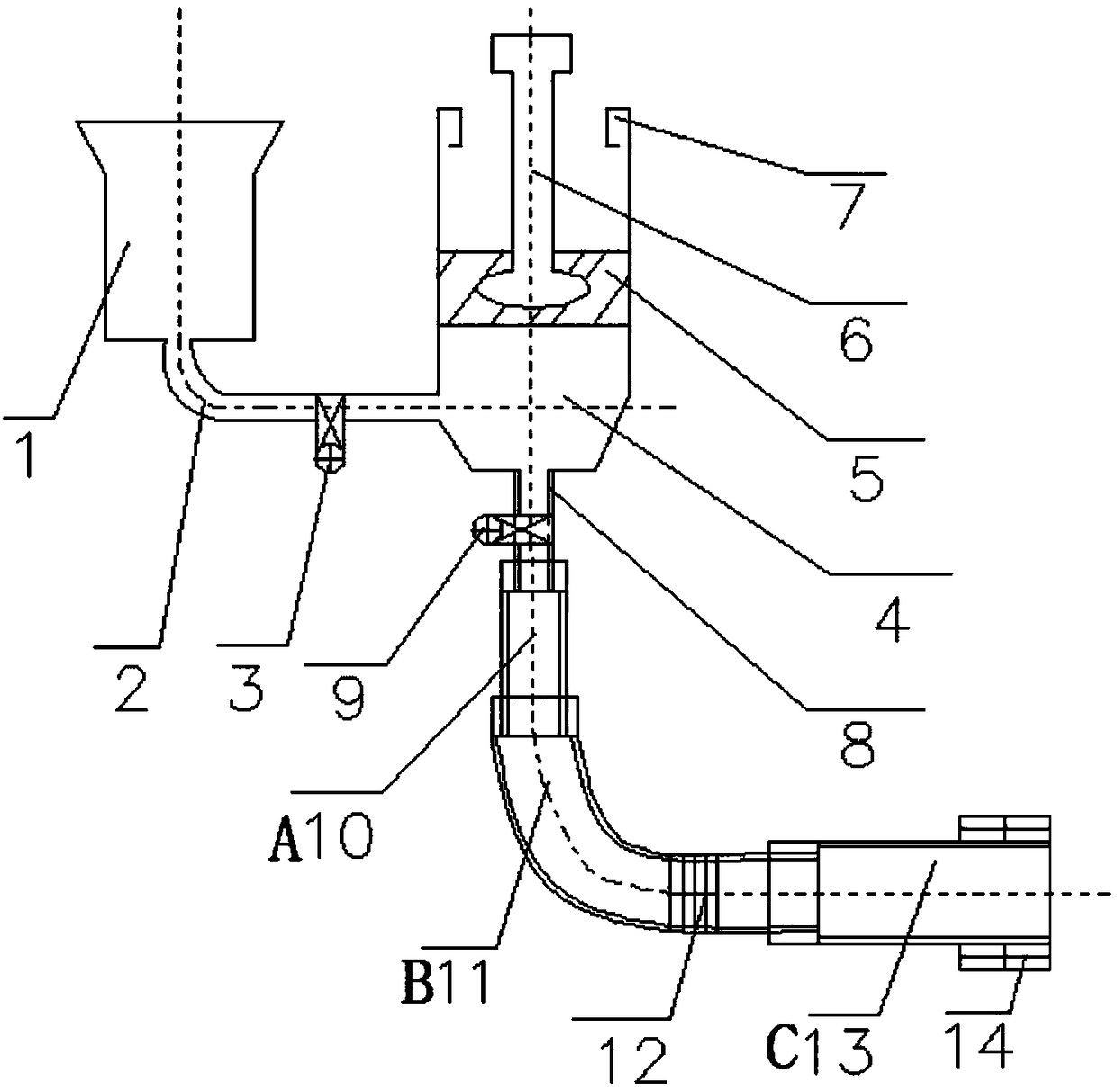
[0030] A. Pour 15kg or 20 or 25kg of granular bentonite into feed tank 1;

[0031] B. Open the pumping valve 3, close the suction valve 9, and move the piston rod 6 up and down to press the bentonite particles in the feed tank into the discharge tank 4 by atmospheric pressure;

[0032] C. As the piston rod 6 moves up and down, the lubricating oil box 7 on both sides of the discharge tank 4 will squeeze out a small amount of lubricating oil due to the effect of atmospheric pressure;

[0033] D. When the discharge tank 4 is full of bentonite and the piston rod 6 is difficult to press down, stop moving the piston rod 6;

[0034] E, open the vibrator 12 in the middle and the vibrator 14 at the end of the discharge port;

[0035] F. Then open the suction valve 9, close the pumping valve 3, and push the piston rod 6 to pump out the granular bentonite in the discharge tank 4 to achieve the purpose of pumping the granula...

Embodiment 2

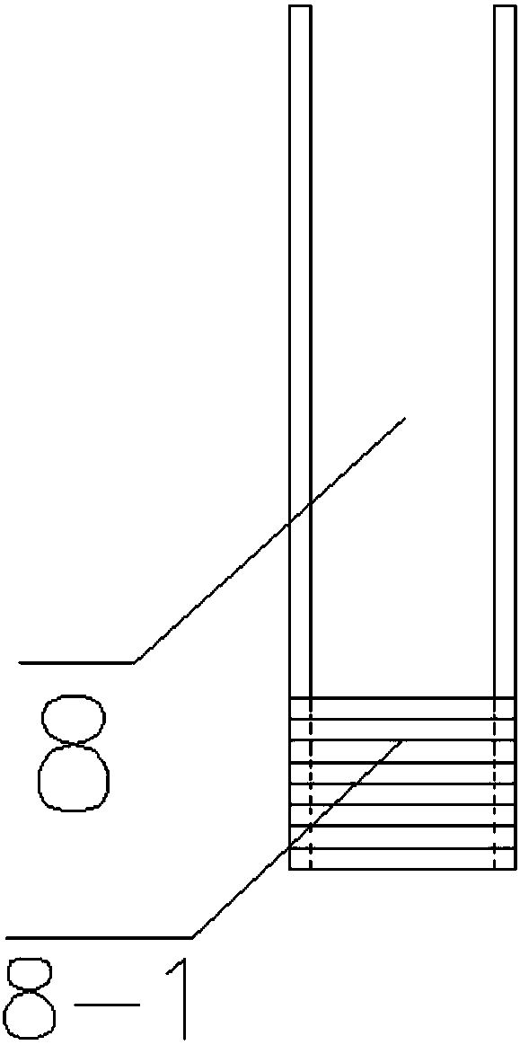
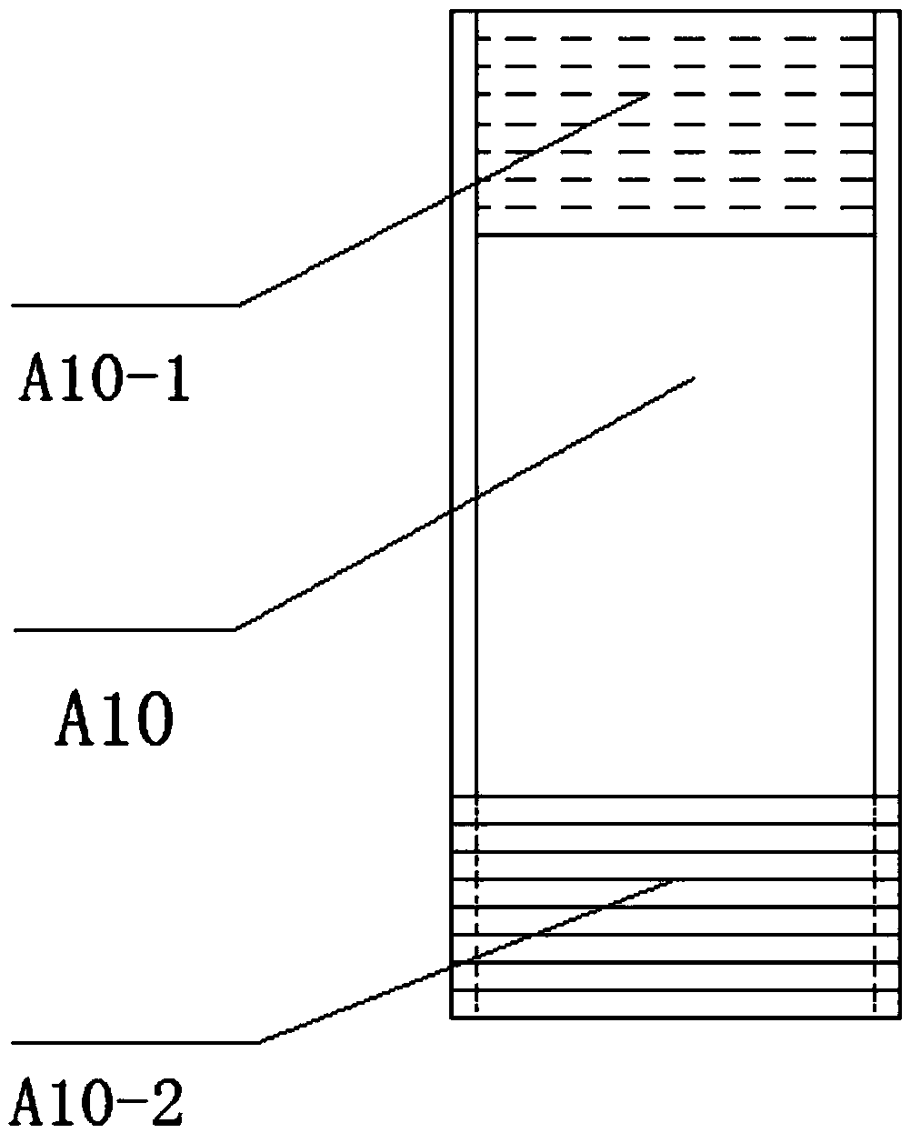
[0038] according to figure 1 , figure 2 , image 3 , Figure 4 , Figure 5 It can be seen that a device for pumping granular bentonite consists of a feed tank 1, a suction pipe 2, a pump valve 3, a discharge tank 4, a piston 5, a piston rod 6, a lubricating oil box 7, and a pump discharge pipe. 8. Pumping discharge pipe outer pattern steel sleeve 8-1, single-section discharge pipe A10, single-section discharge pipe A10 inner-grain steel sleeve A10-1, single-section discharge pipe A10 outer-grain steel sleeve A10-2, Single-section discharge pipe B11, single-section discharge pipe B11 inner thread steel sleeve B11-1, single-section discharge pipe B11 outer-grain steel sleeve B11-2, middle vibrator 12, single-section discharge pipe C13, single-section outlet Material pipe C13 is composed of inner grain steel sleeve C13-1 and end vibrator 14. The connection relationship is: feed tank 1 and discharge tank 4 are fixedly connected through suction pipe 2, and pumping valve is arr...


PUM


Abstract

The invention discloses a method and a device for pumping particle bentonite. The method comprises the following steps: (A) the particle bentonite is poured into a feeding tank; (B) a pumping valve isopened; a sucking valve is closed; and a piston rod moves up and down; (C) along with up-down movement of the piston rod, lubricating oil is extruded from lubricating oil boxes on the two sides of adischarge tank; (D) after the discharge tank is fully filled with the bentonite, the piston rod is downwards pressed; (E) a middle vibrator and a discharge port end vibrator are opened; and (F) the sucking valve is opened; and the pumping valve is closed. The feeding tank and the discharge tank are connected through a sucking pipe; the piston rod is embedded into a piston; the discharge tank is connected with a pumping discharge pipe; the pumping discharge pipe is connected with a single-section discharge pipe; the single-section discharge pipe is connected with a single-section discharge pipe; and the tail end of the single-section discharge pipe is connected with the end vibrator. The method is easy to realize and convenient to operate, and needs no heavy mechanical force for compaction.The device is simple in structure and convenient to use, can use an atmospheric pressure effect for uniformly and densely filling bentonite particles in grooves in underground diaphragm walls, and islow in cost and convenient to construct and operate.

Description

technical field [0001] The invention belongs to environmental geotechnical engineering, and more specifically relates to a method for pumping granular bentonite, and also relates to a device for pumping granular bentonite, which is suitable for the construction of anti-seepage layers in environmental geotechnical engineering. Background technique [0002] Pumping devices are widely used in construction machinery for pumping concrete, mud and other materials. But at present there is no device for pumping granular bentonite that can be operated easily and with low cost. Lubrication between pistons, granular bentonite can be filled densely, granular bentonite will not block the discharge pipe during pumping, and to ensure that the material can be pumped into some tortuous grooves, it is necessary to apply lubrication between the material cylinder and the material piston Oil, vibrators are installed in the middle and end of the discharge pipe, and the discharge pipe can be bent...

Claims


Application Information

Patent Timeline
Patent Type & Authority Applications(China)
IPC IPC(8): E02D15/02
CPCE02D15/02E02D2250/0023E02D2300/004
Inventor 付伟何斌王云张晶余顺新卢傲刘帅
Owner CCCC SECOND HIGHWAY CONSULTANTS CO LTD
Why Eureka
Try Eureka