Supercharge Your Innovation With Domain-Expert AI Agents!

Novel grouting system and grouting technology for effectively controlling land subsidence

A technology of ground subsidence and grouting system, applied in underground chambers, wellbore linings, tunnel linings, etc., can solve the problems of difficult settlement, effective control of land subsidence, etc., to prevent further expansion of subsidence, avoid land subsidence, and achieve ideal results. Effect

Active Publication Date: 2018-05-22
URBAN MASS TRANSIT ENG CO LTD OF CHINA RAILWAY 11TH BUREAU GRP +1
View PDF7 Cites 0 Cited by
  • Summary
  • Abstract
  • Description
  • Claims
  • Application Information

AI Technical Summary

Problems solved by technology

However, there is an unavoidable problem with this method, that is, when the shield machine is excavating, the excavation section of the excavation cutter head is slightly larger than the outer diameter of the shield, and larger than the outer diameter of the segment, and the gap outside the shield body cannot be cut in time during the excavation process. Filling, if the geological conditions are poor, the ground subsidence will occur because the gap outside the shield cannot be filled in time, and when the stratum collapses above the cutter head, it is necessary to fill the collapsed place in time and form an effective support, but the shield tail The grouting can’t do anything about it, so that when the shield machine reaches the tail of the shield and reaches the collapse, it needs to advance about 5-6 rings. At this time, the collapse has often passed up a large range or even reached the ground, so: when When the geological conditions are poor or passing through important structures, it is difficult to achieve effective control of settlement by traditional grouting methods

Method used


Image

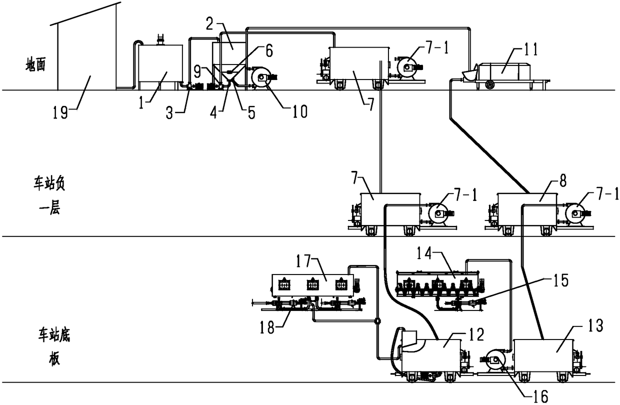
  • Novel grouting system and grouting technology for effectively controlling land subsidence
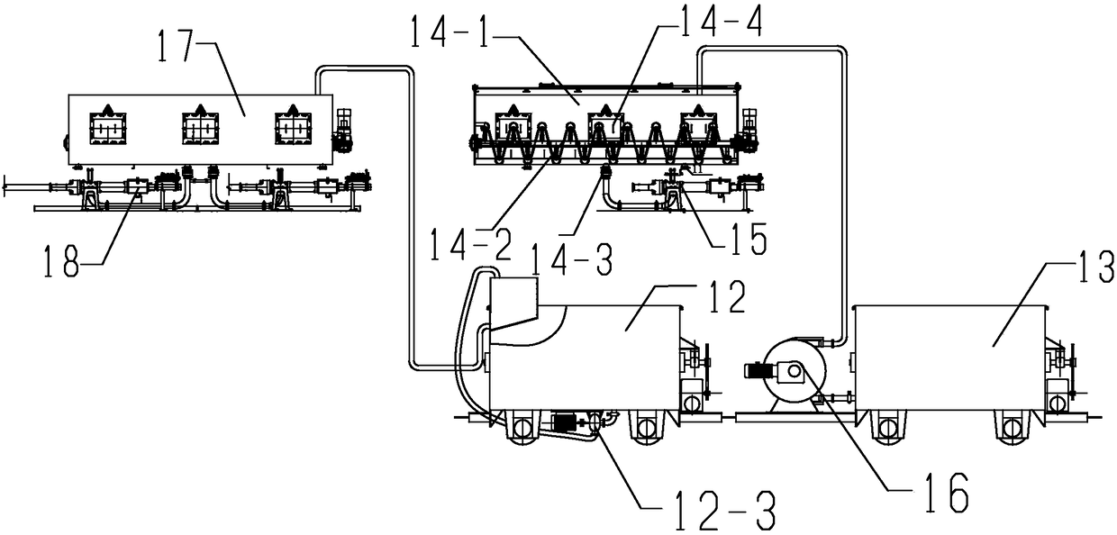
  • Novel grouting system and grouting technology for effectively controlling land subsidence
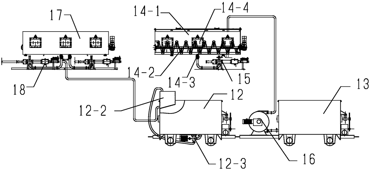
  • Novel grouting system and grouting technology for effectively controlling land subsidence

Examples


Embodiment 1

[0032] Embodiment 1: This embodiment is aimed at the machine-weighted section of the Shenzhen World Convention and Exhibition Center. The stratum in this shield section passes through four subway operation lines in the upper soft and lower hard strata, which has extremely high requirements for settlement control and difficult shield tunneling construction. The settlement control of the upper soft and lower hard strata itself is a major problem in the field of shield tunneling construction, and the construction of the upper soft and lower hard stratum passing through the existing line is even more difficult. There is a project in Shenzhen that passes through an unoperated subway line in a similar stratum. The settlement control has seriously exceeded the standard, and the post-processing is difficult and expensive. The inventor adopts the method among the present invention to carry out timely radial grouting, and its specific process steps are as follows:

[0033] (1) Prepare n...


PUM


Abstract

The invention provides a novel grouting system and method for effectively controlling land subsidence. The novel grouting system includes a slurry stirring device, a slurry conveying device, a shieldtail synchronous injection mortar system, and an inert slurry synchronous grouting system. The inert slurry synchronous grouting system includes a third extrusion pump disposed at a discharge port ofa high build truck, an inert slurry tank, and an inert slurry injection pump disposed at a discharge port of the inert slurry tank, wherein the inert slurry tank consists of a tank body and a stirringdevice arranged in the tank body, a slurry outlet is formed at the bottom of the tank body, and the tank body is provided with a slurry inlet and multiple observation windows; the high build truck communicates with the slurry inlet of the inert slurry tank through the third extrusion pump and a slurry transportation tube; and during the excavation process, at the end of each tunneling cycle, conventional simultaneous grouting of shield tail mortar is carried out through a shield tail mortar grouting system, and at the same time, shield grouting is performed on two radial straight holes from the nearest 12 point position of a shield body through the inert slurry grouting system. The novel grouting system and method avoids the occurrence of land subsidence due to the fact that voids outsidethe shield body cannot be filled in time by means of synchronously injecting novel inert slurry.

Description

technical field [0001] The invention relates to the technical field of tunnel shielding, in particular to a novel grouting process capable of effectively controlling settlement when passing through important structures and a grouting system used in the process. Background technique [0002] In recent years, subway transportation has gradually become an important means to solve traffic congestion in cities, and the shield method, as the main construction method of subway construction, has been more and more widely used. In urban construction, ground subsidence control is the first factor to ensure the safety of ground structures. With the expansion and improvement of the subway transportation network, it is inevitable that subway tunnels need to pass through more structures and even operate subway lines under complex geological conditions. , which puts forward higher requirements for the ground subsidence control technology of shield construction. [0003] The surface subsid...

Claims


Application Information

Patent Timeline
Patent Type & Authority Applications(China)
IPC IPC(8): E21D11/10E21D9/06C04B28/10C04B111/70
CPCE21D9/0671E21D11/10C04B28/10C04B2111/70C04B2111/00146C04B14/06C04B18/08C04B14/104
Inventor 张志冰万维燕曾恕辉龙华东杨梅李应姣刘国建
Owner URBAN MASS TRANSIT ENG CO LTD OF CHINA RAILWAY 11TH BUREAU GRP
Features
  • R&D
  • Intellectual Property
  • Life Sciences
  • Materials
  • Tech Scout
  • Unparalleled Data Quality
  • Higher Quality Content
  • 60% Fewer Hallucinations
Learn More