Double-ridged horn antenna based on specially-shaped ridge loading

A ridged horn, special-shaped technology, applied in the direction of antenna, waveguide horn, antenna grounding switch structure connection, etc., can solve the problems of stiff transition and gain sag, and achieve the effect of smooth transition of impedance transformation and good impedance matching characteristics.

Active Publication Date: 2018-05-22
XIDIAN UNIV +1
View PDF10 Cites 5 Cited by
  • Summary
  • Abstract
  • Description
  • Claims
  • Application Information

AI Technical Summary

Problems solved by technology

However, since the transition between its mouth and face is stil

Method used


Image

  • Double-ridged horn antenna based on specially-shaped ridge loading
  • Double-ridged horn antenna based on specially-shaped ridge loading
  • Double-ridged horn antenna based on specially-shaped ridge loading

Examples


Embodiment 1

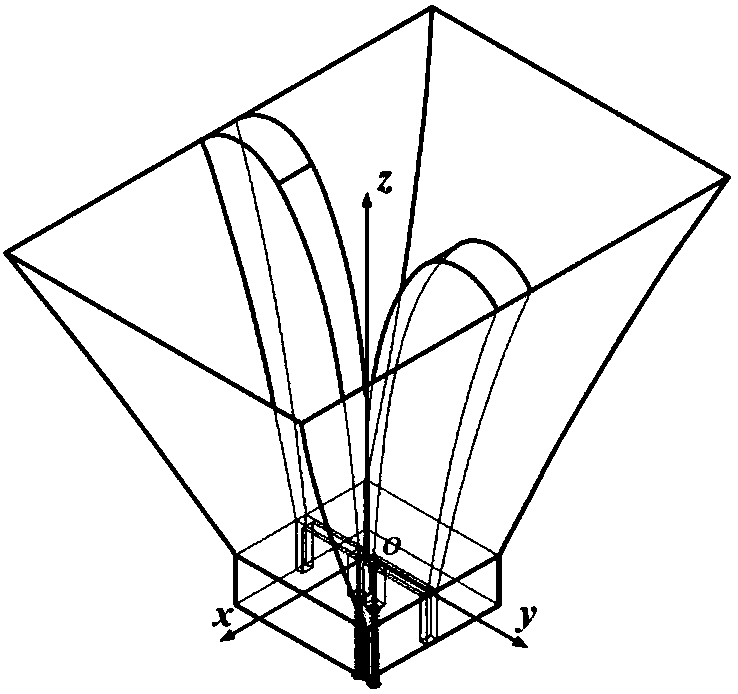
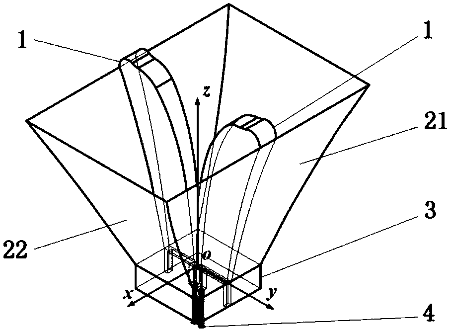
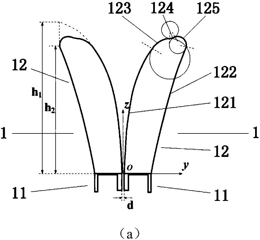
[0040] refer to figure 2 , a double-ridge horn antenna based on special-shaped ridge loading, including two oppositely arranged special-shaped ridge plates 1, a horn housing 2, a back cavity 3 and a feeding coaxial line 4, and the special-shaped ridge plate 1 includes a back cavity matching section 11 and The special-shaped transition section 12; the ridge line of the special-shaped transition section 12 is smoothly connected by two sections of exponential curves and three sections of arcs; A rectangular horn structure formed by splicing each other, wherein the curvature of the curved metal wall 21 is the same as that of the second exponential curve 122; 40mm×13mm cuboid structure; the open end of the back chamber 3 is connected to the bottom end of the speaker housing 2, and the two special-shaped ridge plates 1 are respectively loaded on different curved metal walls 21, and the feed coaxial line 4 The shielding layer is connected to the back cavity 3 , and the inner core p...

Embodiment 2

[0046] The structure of this embodiment is the same as that of Embodiment 1, only the distance d between the two ridges of the two oppositely arranged special-shaped ridges 1 and the thickness t of the special-shaped gradual change section 12 1 and t 2 , the first exponential curve 121 gradient curvature control variable h 1 , second exponential curve 122 gradient curvature control variable h 2 and the parameters of the three arcs have been adjusted:

[0047] The double-ridge spacing d=1mm of the special-shaped ridge plate 1; the thickness of the special-shaped gradual change section 12 is from bottom to top by t 1 = 1mm uniform gradient to t 2 =5mm; its first exponential curve expression is h 1 =80mm, the expression of the second exponential curve is h 2 =75mm, (y of the center control point coordinates corresponding to the first arc segment 123 1 ,z 1 ) is (27.1mm, 65mm), and its radius is r 1 =11mm, (y of the center control point coordinates corresponding to the...

Embodiment 3

[0049] The structure of this embodiment is the same as that of Embodiment 1, only the distance d between the two ridges of the two oppositely arranged special-shaped ridges 1 and the thickness t of the special-shaped gradual change section 12 1 and t 2 , the first exponential curve 121 gradient curvature control variable h 1 , second exponential curve 122 gradient curvature control variable h 2 and the parameters of the three arcs have been adjusted:

[0050] The double-ridge spacing d=3mm of the special-shaped ridge plate 1; the thickness of the special-shaped gradual change section 12 is from bottom to top by t 1 = 4mm uniform gradient to t 2 =50mm; its first exponential curve expression is h 1 =120mm, the expression of the second exponential curve is h 2 =95mm; (y of the center control point coordinates corresponding to the first arc segment 123 1 ,z 1 ) is (42.3mm, 96mm), and its radius is r 1 =16mm, (y of the center control point coordinates corresponding to t...


PUM


Abstract

The invention provides a double-ridged horn antenna based on specially-shaped ridge loading. While the matching characteristics in the working frequency band of the double-ridged horn antenna are ensured, the gain radiation characteristics of the antenna are enhanced. The antenna comprises two oppositely-arranged specially-shaped ridge plates, a horn shell, a back cavity and two feed coaxial lines, wherein each specially-shaped ridge plate comprises a back cavity matching section and a specially-shaped transition section, and the ridge line of the specially-shaped transition section is formedby two exponential curve sections and three arc sections in smooth connection; the horn shell adopts a rectangular horn structure formed by a pair of curved surface metal walls and a pair of plane metal walls in a mutual splicing mode; the two specially-shaped ridge plates are loaded to different curved surface metal walls; the back cavity adopts a cuboid thin wall structure; and the shielding layer of the feed coaxial line is connected with the back cavity, and the inner core passes through the sealing end of the back cavity to be connected with the back cavity matching section. The double-ridged horn antenna based on specially-shaped ridge loading has an ultra wide working frequency band, and can be applied to fields such as communication, remote sensing and antenna measurement.

Description

technical field [0001] The invention belongs to the technical field of antennas, and relates to a double-ridge horn antenna, in particular to an ultra-wideband double-ridge horn antenna based on a special-shaped ridge structure, which can be applied to the fields of communication, remote sensing, antenna measurement and the like. Background technique [0002] With the rapid development of modern wireless communication technology, many communication devices need to have the characteristics of being able to work in a wider frequency band, and all wireless communication systems rely on antennas as radio wave transceivers. UWB antenna has been widely used in the fields of satellite communication, satellite navigation, remote sensing, Doppler and radar because of its superior broadband characteristics. [0003] The technology of using microwave equipment to detect and receive the electromagnetic radiation and scattering characteristics of the measured object in the microwave band...

Claims


Application Information

Patent Timeline
IPC IPC(8): H01Q13/02H01Q1/50
CPCH01Q1/50H01Q13/0275Y02D30/70
Inventor 姜文俞亚庆张哲洪涛龚书喜
Owner XIDIAN UNIV
Why Eureka
Try Eureka