Reconfigurable Sensing Antenna Based on Contactless Rotational Coupling

An antenna and sensing technology, which is applied in the field of reconfigurable sensing antennas, can solve the problems of battery pollution, multiple manpower and material resources, and easily endanger the safety of people, and achieves a simple feeding structure, reduces backward radiation, and enhances forward direction. effect of radiation

Active Publication Date: 2020-06-12
TSINGHUA UNIV
View PDF6 Cites 0 Cited by
  • Summary
  • Abstract
  • Description
  • Claims
  • Application Information

AI Technical Summary

Problems solved by technology

Such mechanical dials need to be read manually at close range. In special environments (dangerous environments such as high temperature and high pressure, or insufficient manpower in large-scale pipelines), this kind of instrument has great disadvantages: First, dangerous environments are not suitable for humans to enter. Distance reading is easy to endanger people's safety; second, the reading of large-scale instruments requires more manpower and material resources
[0004] At present, there are also some occasions where digital active sensors are used. These sensors need to carry batteries, which also have three disadvantages: first, the size of the sensor cannot be further reduced, and cannot be used in some special environments; second, the battery power limits the effective time of the sensor , the battery needs to be replaced frequently; the third is that active devices in high-risk environments are more likely to be affected by the environment, and battery damage is likely to cause huge battery pollution

Method used


Image

  • Reconfigurable Sensing Antenna Based on Contactless Rotational Coupling
  • Reconfigurable Sensing Antenna Based on Contactless Rotational Coupling
  • Reconfigurable Sensing Antenna Based on Contactless Rotational Coupling

Examples


Embodiment Construction

[0033] The present invention will be described below with reference to the accompanying drawings.

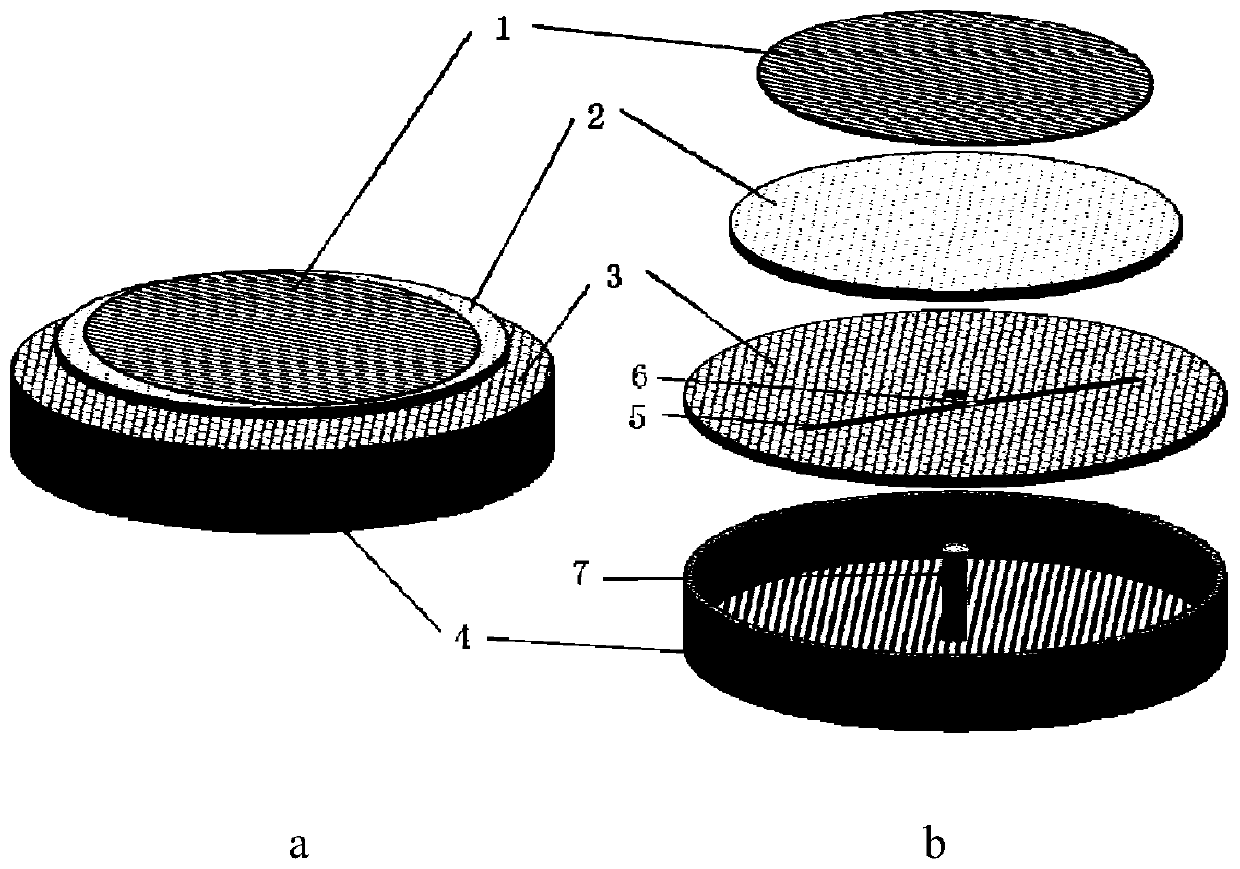
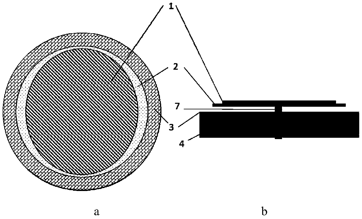
[0034] like figure 1 a, 1b and 2a, 2b. The present invention proposes a reconfigurable sensing antenna based on non-contact rotational coupling, which includes, from top to bottom: a metal patch 1, a dielectric plate 2, a ground plate 3, and a back cavity 4; wherein, the back cavity is the top A cylindrical cavity with an empty surface, the ground plate is used as the upper surface of the column to match with the back cavity, the ground plate is etched with a feeding slot 5 to connect with the RFID chip 6, and the center of the back cavity is provided with a support shaft 7 and the medium The plates are connected, the metal patch is close to the medium plate, and the supporting shaft drives the metal patch to move relative to the feeding slot through the medium plate. The feed slot is excited by the RFID chip to generate a radiation field, which is coupled to the metal patch, ...


PUM


Abstract

The invention, which belongs to the technical field of antennas, particularly relates to a reconfigurable sensing antenna based on non-contact rotational coupling. The antenna is composed of a metal patch, a dielectric plate, a grounding plate and a back cavity that are arranged successively from top to bottom. The back cavity is a cylindrical cavity with the empty upper top surface. The groundingplate is connected with the back cavity in a matching manner as the upper top surface of the cylinder; and a feed slot is etched in the grounding plate and is connected with an RFID chip. A support rotating shaft is arranged at the center of the back cavity and is connected with the dielectric plate. The metal patch is in close contact with the dielectric plate; and the support rotating shaft drives the metal patch by the dielectric plate to move relatively to the feed slot. The feed slot generates a radiation filed after being excited by the RFID chip and is coupled to the metal patch; the support rotating shaft converts the mechanical rotator of the sensor into the rotation angle of the metal patch, so that the resonant frequency of the antenna is changed; and the reader reads the resonant frequency of the antenna to obtain the mechanical rotator of the sensor.

Description

technical field [0001] The invention belongs to the technical field of antennas, and in particular relates to a reconfigurable sensing antenna based on non-contact rotational coupling. Background technique [0002] Nowadays, people pay attention to changes in the natural environment, and there are a large number of sensors used for environmental monitoring, such as temperature, humidity, pressure, etc. With the development of technology, more and more environmental variables can be monitored, and sensors tend to be miniaturized. Digital, intelligent, multi-functional, systematic and networked. [0003] In practical sensor applications, various mechanical sensors, such as bimetal thermometers, water pressure gauges, barometers and other sensors that rely on pointers to indicate the dial still occupy a large proportion. Such a mechanical dial needs to be manually read at a close distance. In special environments (dangerous environments such as high temperature and high pressu...

Claims


Application Information

Patent Timeline
Patent Type & Authority Patents(China)
IPC IPC(8): H01Q1/38H01Q1/48H01Q1/50H01Q1/22
CPCH01Q1/22H01Q1/38H01Q1/48H01Q1/50
Inventor 杨帆董凯明许慎恒李懋坤
Owner TSINGHUA UNIV
Why Eureka
Try Eureka