Automatic-discharging type steel pipe cutting device

A technology of automatic blanking and cutting devices, which is applied in the direction of pipe shearing devices, shearing devices, and accessories of shearing machines, etc., and can solve the unsolved problems of automatic blanking and low efficiency

Inactive Publication Date: 2018-05-25
天津市宝利华峰五金制品有限公司
View PDF0 Cites 6 Cited by
  • Summary
  • Abstract
  • Description
  • Claims
  • Application Information

AI Technical Summary

Problems solved by technology

[0002] Pipe cutting machine is a commonly used hardware processing device. It is often used for cutting steel pipes, aluminum pipes or other profiles. A sleeve and a locking sleeve, the guide sleeve and the locking sleeve are respectively formed with accommodating passages for passing through the steel pipe, and the positions of the two accommodating passages of the guide sleeve and the positioning sleeve are corresponding. An electric saw is installed above the gap between the tight sleeves to cut steel pipes or other profiles, but the loading and unloading of the above-mentioned pipe cutting machine requires manual advancement of steel pipes or profiles during use, so the efficiency is very low
[0003] In order to solve the shortcomings of the above-mentio...

Method used


Image

  • Automatic-discharging type steel pipe cutting device
  • Automatic-discharging type steel pipe cutting device
  • Automatic-discharging type steel pipe cutting device

Examples


Embodiment Construction

[0015] Below in conjunction with the examples, the present invention is further described, the following examples are illustrative, not limiting, and the protection scope of the present invention cannot be limited by the following examples.

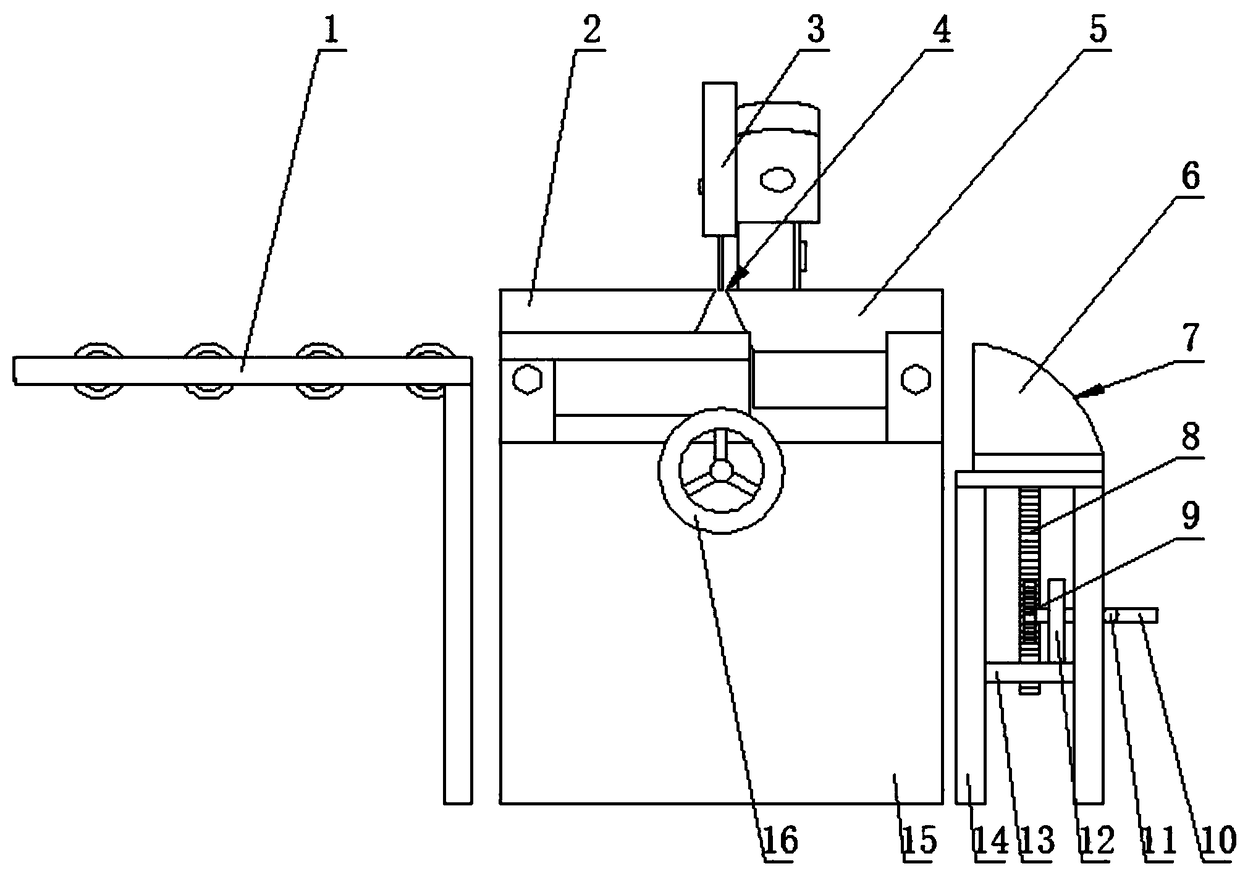
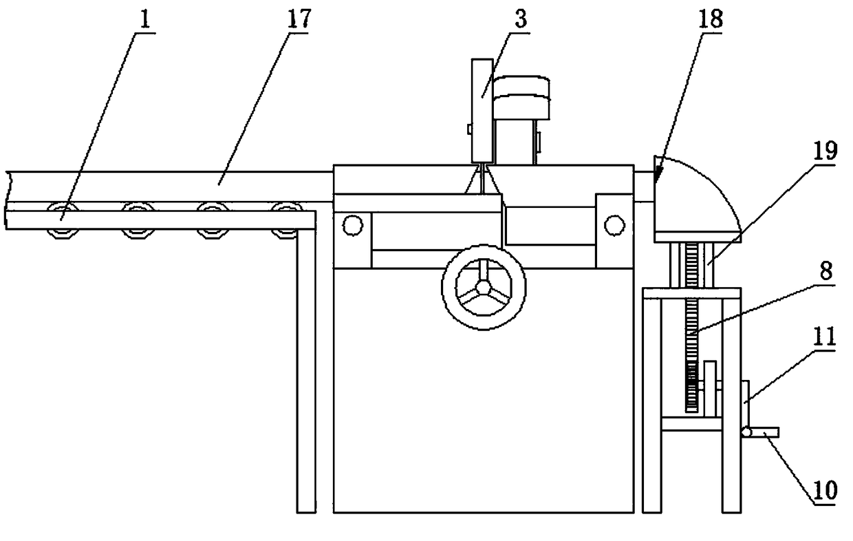
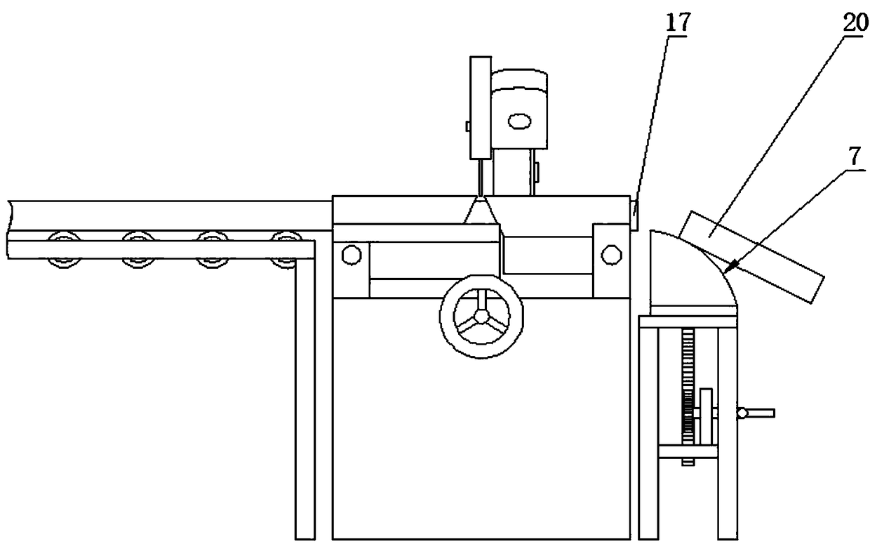
[0016] A steel pipe cutting device for automatic blanking, including a machine base 15, a guide sleeve 2 and a locking sleeve 5 are respectively installed at intervals on the left and right sides of the upper end of the machine base, and a gap is formed between the guide sleeve and the locking sleeve 4. An electric saw is installed above the gap. 3. The guide sleeve and the locking sleeve are respectively formed with accommodating passages for passing through the steel pipe. The positions of the two accommodating passages of the guide sleeve and the positioning sleeve are corresponding. A handle 16 for adjusting the inner diameter of the accommodating channel is installed in the end face of the frame next to the sleeve and the positioning ...


PUM


Abstract

The invention relates to the field of hardware machining device, in particular to an automatic-discharging type steel pipe cutting device. An automatic discharging device for a pipe cutter comprises abase; a guide sleeve and a locking sleeve are separately installed at the left and right sides of the upper end of the base in a spaced manner; the guide sleeve and the locking sleeve are separatelyinternally provided with accommodating passages for a steel pipe to pass through; the two accommodating passages of the guide sleeve and a positioning sleeve correspond to each other in position; a conveying device is installed at one side of a feeding end of the guide sleeve and is used for pushing the steel pipe into the accommodating passage formed in the guide sleeve; a frame is installed by the side of a discharging end of the positioning sleeve; an air cylinder is horizontally installed inside the upper end face of the frame; a limiting block is installed at a piston rod of the air cylinder; the horizontal position of the limiting block and the discharging end of the locking sleeve are positioned in the same horizontal plane; when the air cylinder is in an outwards-moving state, thelimiting block is positioned at a corresponding position at the front end of the locking sleeve; and when the air cylinder is in a returning state, the limiting block is positioned by the side of thelocking sleeve.

Description

technical field [0001] The invention relates to the field of hardware processing devices, in particular to a steel pipe cutting device for automatic blanking. Background technique [0002] Pipe cutting machine is a commonly used hardware processing device. It is often used for cutting steel pipes, aluminum pipes or other profiles. A sleeve and a locking sleeve, the guide sleeve and the locking sleeve are respectively formed with accommodating passages for passing through the steel pipe, and the positions of the two accommodating passages of the guide sleeve and the positioning sleeve are corresponding. An electric saw is installed above the gap between the tight sleeves to cut steel pipes or other profiles, but the above-mentioned pipe cutting machine needs to manually push the steel pipes or profiles during loading and unloading, so the efficiency is very low. [0003] In order to solve the shortcomings of the above-mentioned devices, some manufacturers have also improved ...

Claims


Application Information

Patent Timeline
IPC IPC(8): B23D21/00B23D33/02B23D33/10
CPCB23D21/00B23D33/02B23D33/10
Inventor 董克贤
Owner 天津市宝利华峰五金制品有限公司
Why Eureka
Try Eureka