Supercharge Your Innovation With Domain-Expert AI Agents!

A multifunctional mechanical workbench capable of multi-angle machining work

A multi-angle and multi-functional technology, applied in the direction of manufacturing tools, other manufacturing equipment/tools, etc., can solve the problems of inconvenient processing, poor operation effect, difficult operation, etc., to improve operation efficiency, convenient operation and time saving. Effect

Active Publication Date: 2019-04-23
肇庆市高要区博斯五金制品有限公司
View PDF5 Cites 0 Cited by
  • Summary
  • Abstract
  • Description
  • Claims
  • Application Information

AI Technical Summary

Problems solved by technology

[0003] The mechanical workbench is one of the commonly used equipment in hardware production. The mechanical workbench for processing work can only be used for grinding or cutting hardware parts. The functionality of the mechanical workbench is poor, and the use is relatively limited. It cannot be better for the work. It provides greater convenience, and the current work does not have a good angle adjustment function, and the orientation of the work is relatively single. For irregular parts, it is inconvenient to process, and the current mechanical workbench does not have a good fixing structure for the parts. It is inconvenient to choose the fixing method according to the type of parts, and the current mechanical workbench cannot choose the operation method according to the specific situation, resulting in poor operation effect and high difficulty, which is easy to affect the efficiency and efficiency of the operation. The effect of homework

Method used


Image

  • A multifunctional mechanical workbench capable of multi-angle machining work
  • A multifunctional mechanical workbench capable of multi-angle machining work
  • A multifunctional mechanical workbench capable of multi-angle machining work

Examples


Embodiment 1

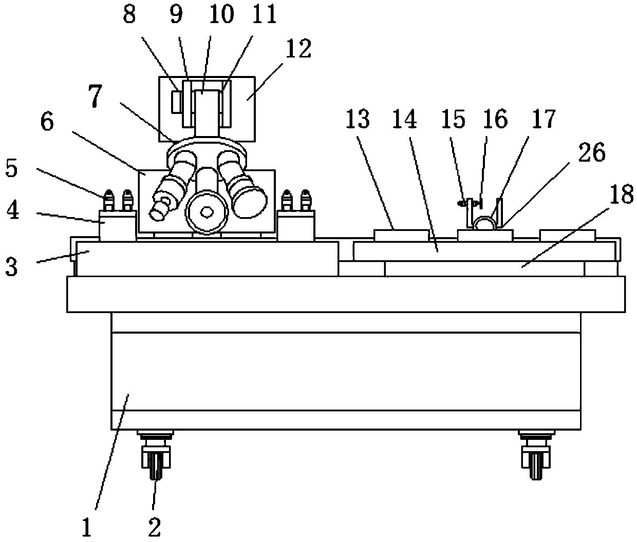
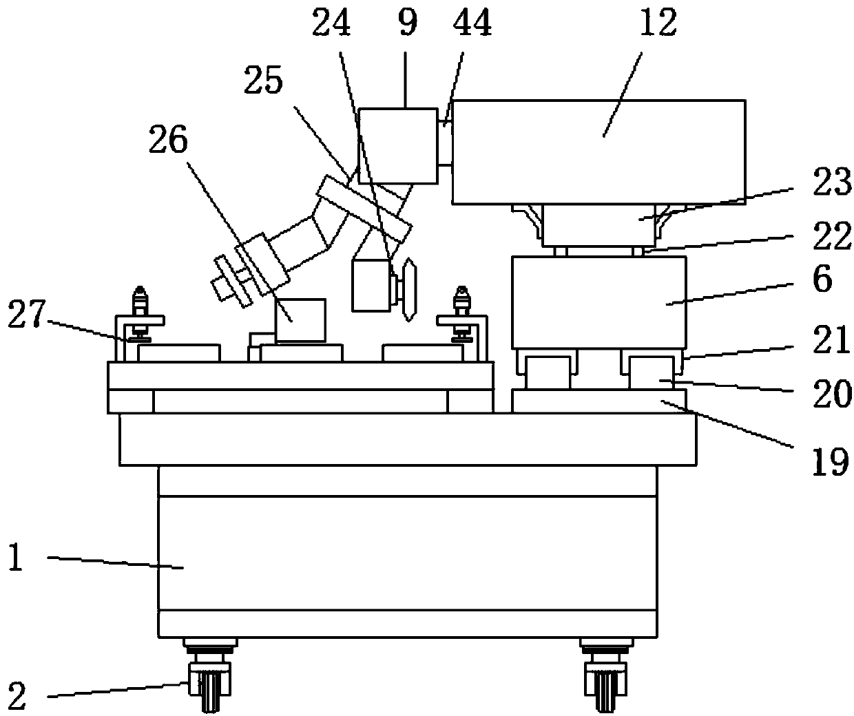
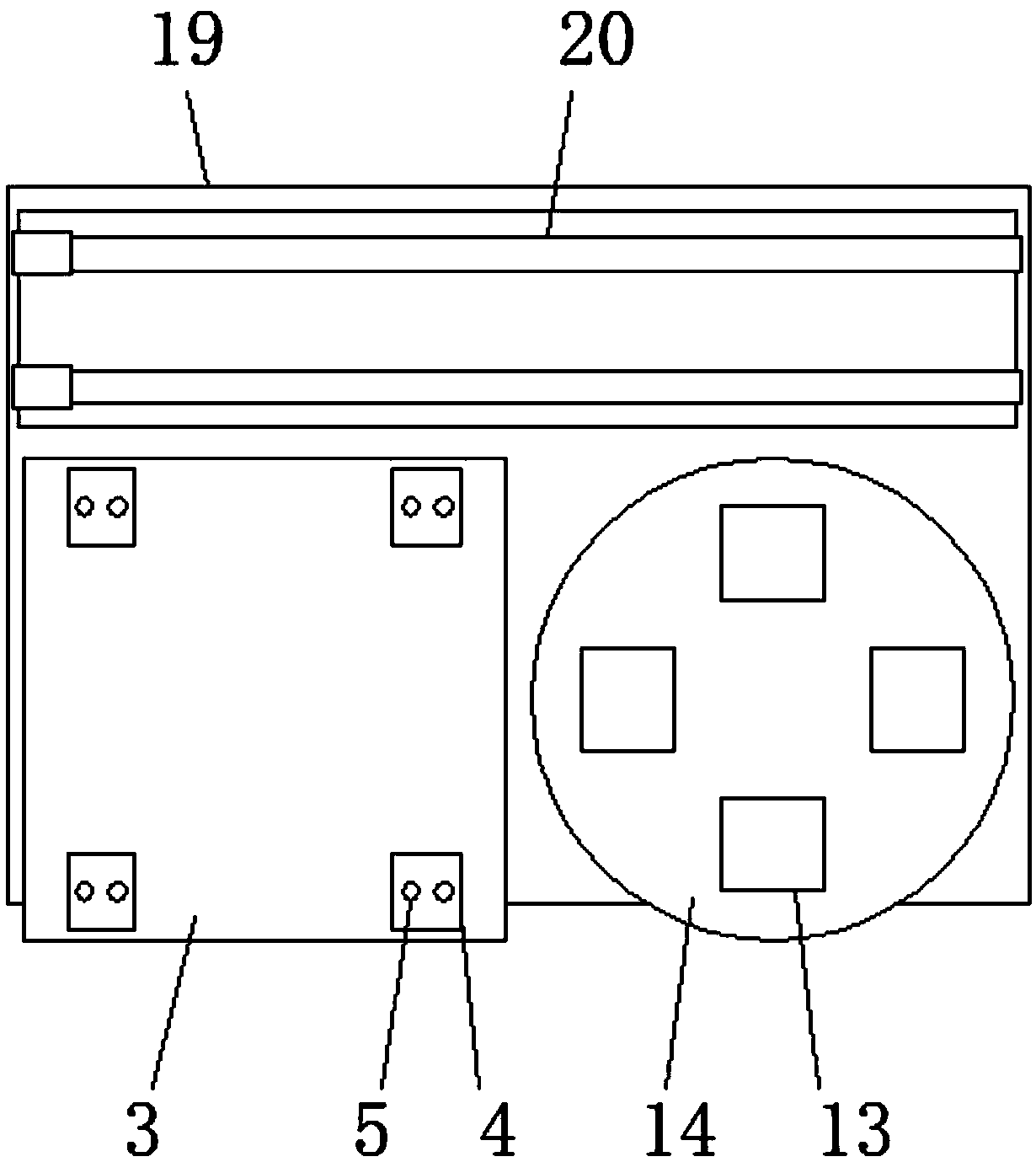
[0027] Example 1, such as figure 1 , Figure 5 First, the cutting object is placed on the cutting table 3, and the object is fixed on the cutting table 3 by the L-shaped splint 4 and the first pneumatic cylinder 5. First, the third rotating motor 25 drives the turntable 7, and the cutting blade 34 is adjusted to the working position. The first electromagnetic slide rail 20 and the first electromagnetic slide block 21 can be used to move to the designated position above the cutting table 3, and the second electromagnetic slide rail 39 and the second electromagnetic slide block 40 make the sliding column 44 slide, further to The position of the cutting blade 34 is adjusted, and then the lifting air cylinder 42 drives the cutting blade 34 to move up and down, so that the cutting blade 34 is in contact with the parts to be cut, and drives the cutting blade 34 to run to cut the parts. And the first electromagnetic slider 21 drives the cutting part to move.

Embodiment 2

[0028] Example 2, such as figure 1 , Figure 4 When the regular object is polished, the grinding piece can be placed inside the placement groove 13, the object is fixed inside the placement groove 13 by the fixed spring 45 and the splint 46, and then passed through the first electromagnetic slide rail 20 and the first electromagnetic slide block 21. Adjust the position of the second mounting base 12, adjust the sliding column 44 with the second electromagnetic slide rail 39 and the second electromagnetic slider 40, so that the working part is located above one of the placement slots 13, driven by the third rotating motor 25 The turntable 7 rotates to adjust the grinding head 31 to the working position. The lifting air cylinder 42 controls the lifting of the working position to adjust the grinding head 31 to a specified height. The first grinding motor 30 drives the first grinding motor 30 to grind the object. At the same time, other stations are loaded. After the polishing is...

Embodiment 3

[0029] Example 3, such as figure 1 , Figure 4 When it is necessary to polish irregular objects, the irregular objects are placed inside the U-shaped splint 26, and the object is fixed by the second air cylinder 15 and the splint 16. The disc 35 is adjusted in the working position, and the grinding head 31 or the grinding disc 35 is driven by the first grinding motor 30 and the second grinding motor 36 respectively to grind the specified position. When grinding at different angles is required, the first The rotating motor 8 drives the rotating shaft 11 to rotate, thereby adjusting the inclination angle of the working part. At the same time, the second rotating motor 17 drives the fixed part to rotate, thereby adjusting the inclination angle of the object. The fourth rotating motor 48 drives the fixed part to rotate, so that different surfaces of the object can be polished.

[0030] Working principle: Before use, move the device to the designated position through the universa...


PUM


Abstract

The invention discloses a multifunctional mechanical working table capable of working in multi-angle mode. The working table comprises a machine tool, a mounting plate is arranged on one side of the machine tool, and first electromagnetic sliding rails are arranged on the two sides above the mounting plate; the top of the first electromagnetic sliding rail is provided with two sets of first electromagnetic sliding blocks, and a first installation base is arranged above the first electromagnetic sliding block; an installation groove is formed in the top of the first installation base, and foursets of lifting pneumatic cylinders are arranged in the installation grooves, the top of the lifting pneumatic cylinder is provided with a piston rod, and the top of the piston rod is provided with afixing block; and a second installation base is arranged at the top of the fixed block, and an installation hole is formed in the inner side of the second installation base. The workbench is providedwith a cutting table and a grinding table, a cutting structure and a grinding structure on the mechanical table cooperate, so that the function of the working table is more comprehensive, the polishing operation of the hardware can be realized, the cutting operation of the hardware can be realized, and the functionality is stronger.

Description

technical field [0001] The invention relates to the technical field of hardware production equipment, in particular to a multifunctional mechanical workbench capable of multi-angle processing. Background technique [0002] Traditional hardware products, also known as "hardware", refer to five metals: gold, silver, copper, iron, and tin. After manual processing, it can be made into works of art or metal devices such as knives and swords. Hardware in modern society is more extensive, such as hardware tools, hardware parts, daily hardware, architectural hardware, and security supplies. With the current market and society With the development of the industry, the use of hardware accessories is becoming more and more extensive, the production demand of hardware is also increasing, and the equipment for various hardware production is becoming more and more perfect. [0003] The mechanical workbench is one of the commonly used equipment in hardware production. The mechanical workb...

Claims


Application Information

Patent Timeline
Patent Type & Authority Patents(China)
IPC IPC(8): B23P23/04
CPCB23P23/04
Inventor 赵战锋
Owner 肇庆市高要区博斯五金制品有限公司
Features
  • R&D
  • Intellectual Property
  • Life Sciences
  • Materials
  • Tech Scout
  • Unparalleled Data Quality
  • Higher Quality Content
  • 60% Fewer Hallucinations
Learn More