

A robot automatic riveting and grinding system
A robot and riveting technology, applied in grinding automatic control devices, grinders, manipulators, etc., can solve the problem that riveting process and post-processing process cannot be comprehensively considered, and achieve the effect of improving riveting efficiency, improving efficiency and improving riveting quality.
- Summary
- Abstract
- Description
- Claims
- Application Information
AI Technical Summary
Problems solved by technology
Method used
Image

Examples
specific Embodiment approach 1
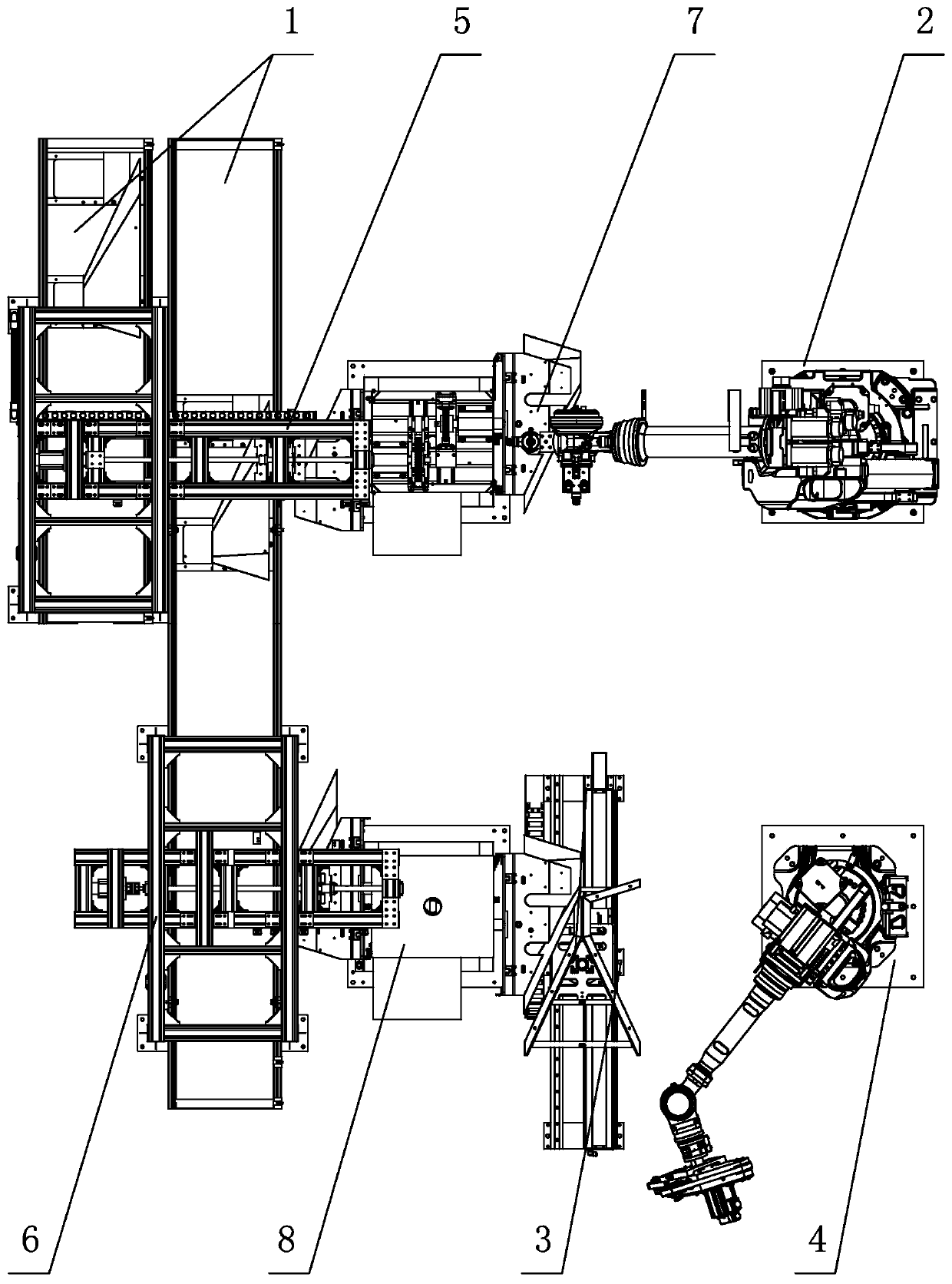
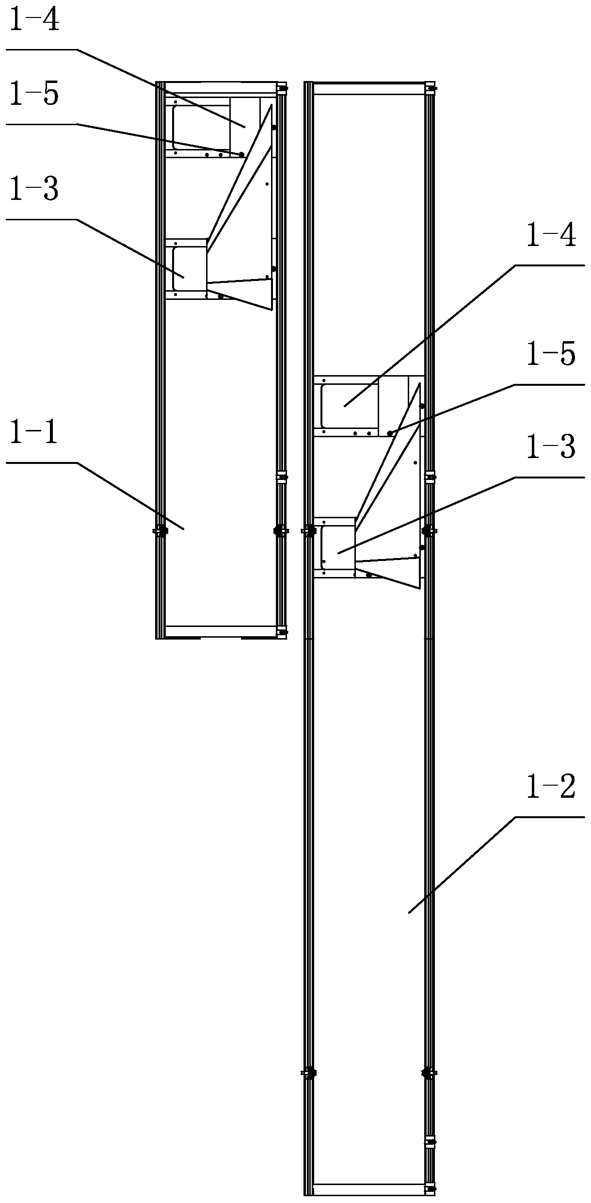
[0014] Specific implementation mode one: combine figure 1 and figure 2 Describe this embodiment, a robot automatic riveting and grinding system of this embodiment, which includes a parts conveying module 1, a parts handling module, a parts clamping and turning module, a parts riveting module 2, a parts grinding protection module 3 and a parts grinding module 4 The parts delivery module 1 includes a first belt conveyor 1-1, a second belt conveyor 1-2, two trays 1-3, two follow-up pads 1-4 and a plurality of limit posts 1-5, The first belt conveyor 1-1 and the second belt conveyor 1-2 are arranged side by side, and the two trays 1-3 are fixedly installed on the belts of the first belt conveyor 1-1 and the second belt conveyor 1-2 respectively. On each tray 1-3, a follower plate 1-4 and a plurality of limit columns 1-5 are respectively installed, and the belts of the first belt conveyor 1-1 and the second belt conveyor 1-2 are Driven by the conveyor motor, the pallets 1-3 move...
specific Embodiment approach 2
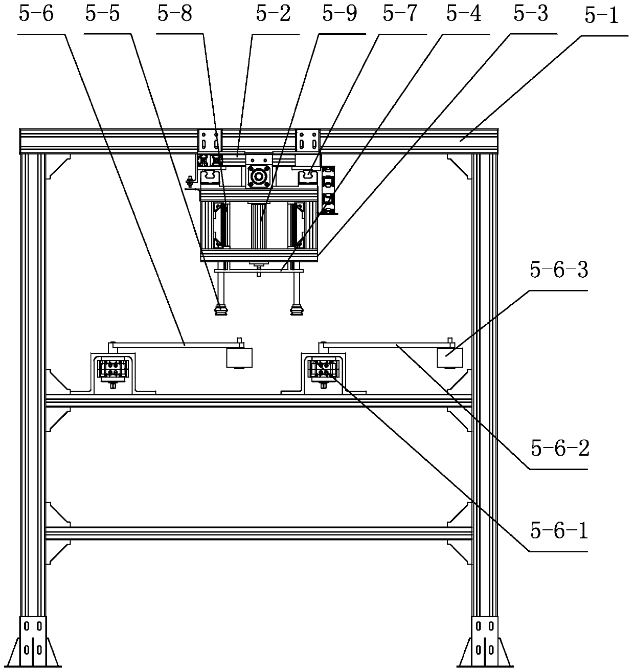
[0016] Specific implementation mode two: combination image 3 and Figure 4Describe this embodiment, the riveting handling module 5 of this embodiment includes a main frame 5-1, a suspension beam frame 5-2, a translation frame 5-3, a translation mechanism, a first elevating frame 5-4, a first elevating mechanism, four A suction cup 5-5 and a swing positioning mechanism 5-6; the translation mechanism includes a translation linear guide 5-7, a translation motor and a translation ball screw pair, and the suspension beam frame 5-2 is fixedly installed on the top of the main frame 5-1, and the translation linear The guide rail 5-7 is fixedly installed on the suspension beam frame 5-2 along the length direction of the suspension beam frame 5-2, the translation frame 5-3 is positioned at the bottom of the suspension beam frame 5-2, and the upper end of the translation frame 5-3 is connected with the translation linear guide rail 5-2. The slide block of 7 is fixedly connected, and th...
specific Embodiment approach 3
[0017] Specific implementation mode three: combination Figure 4 Describe this embodiment, the swing positioning mechanism 5-6 of this embodiment includes two swing positioning units, and the two swing positioning units are installed side by side on the middle beam of the main frame 5-1; each swing positioning unit includes a swing cylinder 5- 6-1, fork 5-6-2 and roller 5-6-3, the fork 5-6-2 is set horizontally, one end of the fork 5-6-2 is rotationally connected with the swing cylinder 5-6-1, and the swing Cylinder 5-6-1 is installed on the middle beam of main frame 5-1, and the other end of fork 5-6-2 is rotatably connected with roller 5-6-3. In this way, the swing cylinder 5-6-1 drives the swing rod 5-6-2 and the roller 5-6-3 to push the wing plate components automatically delivered by the parts delivery module 1, and push the three sides of the wing plate components to the The preliminary positioning of the workpiece is completed on the limit post 1-5. Other compositions...
PUM
 Abstract
Description
Claims
Application Information