Sintered product bearing mechanism

A bearing mechanism and product technology, applied in the field of sintering technology, can solve the problems of low yield rate, easy deformation and fracture of the bearing plate, etc., and achieve the effect of improving yield rate, reducing local stress, and reducing temperature difference

Inactive Publication Date: 2018-05-25
湖南太子新材料科技有限公司
View PDF3 Cites 0 Cited by
  • Summary
  • Abstract
  • Description
  • Claims
  • Application Information

AI Technical Summary

Problems solved by technology

[0004] This application provides a sintered product carrying mechanism to solve the problem t

Method used


Image

  • Sintered product bearing mechanism
  • Sintered product bearing mechanism
  • Sintered product bearing mechanism

Examples


Embodiment Construction

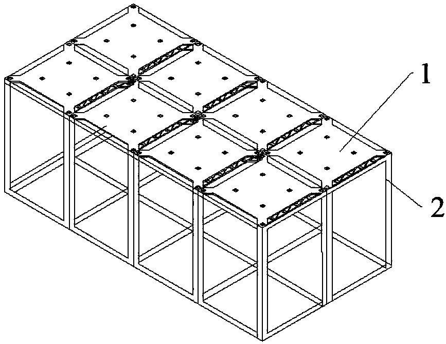
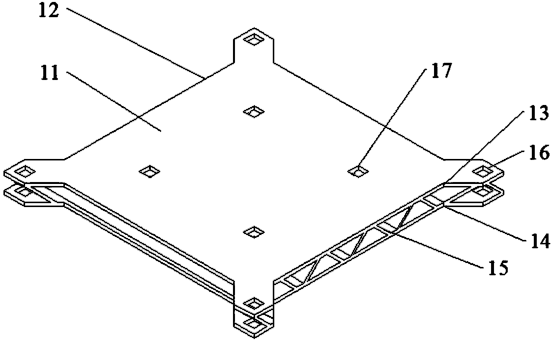
[0027] see figure 1 , is a structural schematic diagram of a sintered product carrying mechanism, composed of figure 1 It can be seen that the sintered product carrying mechanism provided by the present application includes a carrying plate 1 and a sintering frame 2 used in conjunction with the carrying plate 1, wherein the carrying plate 1 includes a square carrying body 11 and a Fire path groove 12 on four sides. In this embodiment, the carrying plate 1 can be made in the following manner. The material of the carrying plate 1 is formed into a square plate-shaped carrying body 1, and then a certain amount of material is cut off from the four sides of the square to form four flames. groove 12, and then through mechanical processing, the edge of the material is polished to a larger rounded corner, and finally formed figure 2 The structure of the carrier plate 1 is shown.

[0028] The carrying body 11 includes a carrier layer 13 in contact with the sintered product, a suppor...


PUM


Abstract

The invention provides a sintered product bearing mechanism comprising bearing plates and a sintering frame. During actual production, the bearing plates are firstly fixed in a supporting frame of thesintering frame, to-be-sintered product green bodies are placed on carrying layers of the bearing plates, the temperature differences between the carrying layers and supporting layers are reduced through flame path holes formed in the bearing plates, and the situation that the bearing mechanism is damaged by stress concentration is avoided. Due to the arrangement of a plurality of reinforcing ribs, spaces capable of transmitting heat are formed between the carrying layers and the supporting layers, the temperatures inside and outside the bearing plates are kept consistent in the sintering temperature-rise process, and the situation that the bearing plates fracture since local high temperature occurs is avoided. Due to the sintered product bearing mechanism provided by the invention, internal local stress can be reduced in the sintering process, the sintering forming process is stable, the yield of sintered products is increased, and the problem that traditional bearing plates are prone to deformation and fracturing and consequently the yield of sintered products is low is solved.

Description

technical field [0001] The present application relates to the technical field of sintering technology, in particular to a sintered product carrying mechanism. Background technique [0002] The sintering process is a product processing process in which the green body made into a finished shape is placed in a high-temperature sintering furnace and formed by calcination. In order to improve the production efficiency of products and ensure the yield rate, in actual production, products of the same batch need to be sintered together. During the sintering process, a plurality of green bodies are usually placed in a high-temperature furnace, and each green body is separated from each other by a certain distance to avoid mutual influence between the green bodies. For products such as sintered plates, the product itself is relatively thin, but the dimensions in other directions are large, so that the products need sufficient spacing, support and protection during the sintering proce...

Claims


Application Information

Patent Timeline
IPC IPC(8): B29C67/04
CPCB29C67/04
Inventor 刘运群
Owner 湖南太子新材料科技有限公司
Why Eureka
Try Eureka