Civil engineering aseismic structure and method thereof

A technology for earthquake-resistant structures and civil engineering, applied in earthquake-proof, building components, building types, etc., can solve the problems of poor ability to consume vibration energy, high cost, difficult construction of seismic isolation layers, etc., so as to improve the seismic effect and reduce the economic effect of loss

Inactive Publication Date: 2018-05-25
LUOYANG INST OF SCI & TECH
View PDF9 Cites 7 Cited by
  • Summary
  • Abstract
  • Description
  • Claims
  • Application Information

AI Technical Summary

Problems solved by technology

[0002] Earthquake is an unavoidable natural phenomenon in human society. The casualties and economic losses caused by earthquakes are huge. Among them, the collapse of buildings during earthquakes is a major factor causing economic losses and casualties. Therefore, all countries are committed to improving civil construction. The anti-seismic ability of the project, the traditional structure anti-seismic design relies on the strength and deformation of the structure itself to resist earthquakes, and ensures that the structure is in an elastic working state under the action of small earthquakes, but under the action of moderate and large earthquakes, the building structure is easily damaged. The general anti-seismic principle is to install a seismic isolation layer between the superstructure and the foundation, so that the deformation during the earthquake is mainly concentrated in the seismic isolation layer, so that the upper building is protected, but the existing seismic isolation structure consumes vibration. The energy capacity is poor, the cost is expensive, and the construction of the seismic isolation layer is difficult, which needs further improvement

Method used


Image

  • Civil engineering aseismic structure and method thereof
  • Civil engineering aseismic structure and method thereof
  • Civil engineering aseismic structure and method thereof

Examples


Embodiment Construction

[0022] Attached below Figure 1-5 , the specific implementation of the present invention will be described in detail, but it should be understood that the protection scope of the present invention is not limited by the specific implementation. Based on the embodiments of the present invention, all other embodiments obtained by persons of ordinary skill in the art without making creative efforts belong to the protection scope of the present invention.

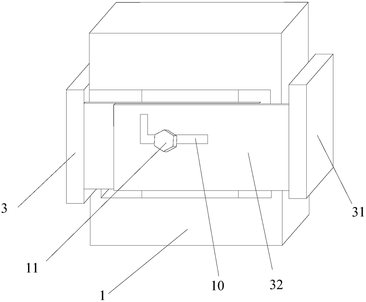
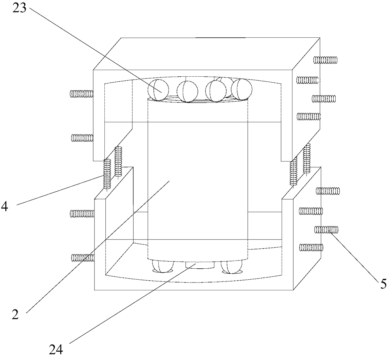
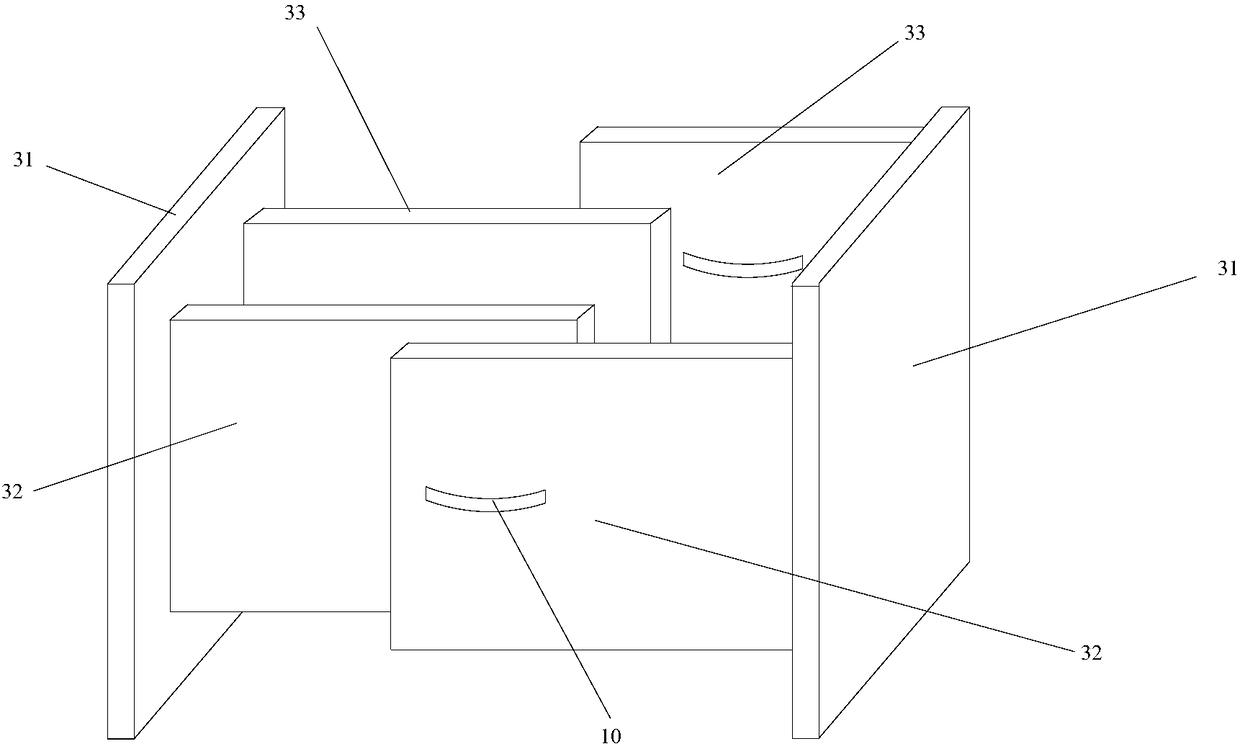
[0023] A civil engineering anti-seismic structure and its method provided by the present invention include: a U-shaped piece 1 arranged relatively up and down, a cylinder structure 2, a protection device 3 arranged opposite to each other on the left and right, a first spring assembly 4 and a second spring assembly 5;

[0024] Such as figure 2 As shown, the joint of the two U-shaped pieces 1 arranged up and down is provided with a first spring assembly 4, and the cylinder structure 2 is arranged inside the space formed by the ...


PUM


Abstract

The invention discloses a civil engineering aseismic structure and a method thereof, and belongs to the technical field of housing construction equipment. The civil engineering aseismic structure includes U-shaped pieces and tube structures which are vertically opposite and protective devices, first spring assemblies and second spring assemblies which are horizontally opposite in a sleeve joint mode; a joint of two U-shaped pieces which are vertically opposite is provided with the first spring assemblies, the tube structures include external tubes, internal tubes, a plurality of elastic ballsand elastic column bodies, and the multiple elastic balls are separately arranged at the upper ends and the lower ends of the external tubes and the internal tubes; and the protective devices includeside plates, front protective plates and rear protective plates, the front protective plates and the rear protective plates are both provided with notches, bolts are arranged in the notches, and the inner sides of the side plates are connected with the U-shaped pieces through the second spring assemblies. The whole civil engineering aseismic structure adopts the characteristic of increased shock resistance from outside to inside, and the purposes of no damage in small shock, repair in middle shock and no collapsing in large shock can be achieved.

Description

technical field [0001] The invention relates to the technical field of building construction equipment, in particular to a civil engineering anti-seismic structure and a method thereof. Background technique [0002] Earthquake is an unavoidable natural phenomenon in human society. The casualties and economic losses caused by earthquakes are huge. Among them, the collapse of buildings during earthquakes is a major factor causing economic losses and casualties. Therefore, all countries are committed to improving civil construction. The anti-seismic ability of the project, the traditional structure anti-seismic design relies on the strength and deformation of the structure itself to resist earthquakes, and ensures that the structure is in an elastic working state under the action of small earthquakes, but under the action of moderate and large earthquakes, the building structure is easily damaged. The general anti-seismic principle is to install a seismic isolation layer betwee...

Claims


Application Information

Patent Timeline
Patent Type & Authority Applications(China)
IPC IPC(8): E04B1/98E04H9/02
CPCE04H9/021
Inventor 赵进东郭卫东雷洋任蓉孙鹏媛乔晓辉吴昌勇曹哲
Owner LUOYANG INST OF SCI & TECH
Why Eureka
Try Eureka