Busbar fixing assembly in high-voltage power distribution system

A high-voltage power distribution and busbar fixing technology, which is applied in the field of detection systems, can solve problems such as excessive tension, economic loss and safety hazards, and affect the stability and safety of power transmission in substations, and achieve the effect of preventing busbar movement

Active Publication Date: 2018-05-25
ELECTRIC POWER RES INST OF GUANGDONG POWER GRID
View PDF5 Cites 2 Cited by
  • Summary
  • Abstract
  • Description
  • Claims
  • Application Information

AI Technical Summary

Problems solved by technology

[0002] Under the influence of different environments, different climates (such as high temperature and heat, rain, snow and freezing), short-circuit faults in the vicinity of the busbar and busbar hardware faults, the tubular busbars in the operation of the substation move due to thermal expansion and contraction. Friction will cause the supporting porcelain bottle below to be under greater stress, shorten the service life of the porcelain bottle, and even cause the busbar pillar porcelain bottle to break.
[0003] The thermal expansion and contraction of the busbar lead to different lengths, causing the busbar to be concave or over-tensioned, which affects the performance of the busbar and the strength of the busbar fixing device. In different environments, if the stretching of the busbar cannot be adjusted in time Monitoring may affect the stability and safety of power transmission in substations, causing large economic losses and potential safety hazards

Method used


Image

  • Busbar fixing assembly in high-voltage power distribution system
  • Busbar fixing assembly in high-voltage power distribution system
  • Busbar fixing assembly in high-voltage power distribution system

Examples


Embodiment Construction

[0030] Below are specific embodiments of the present invention and in conjunction with accompanying drawing, technical scheme of the present invention is described further, but the present invention is not limited to these embodiments.

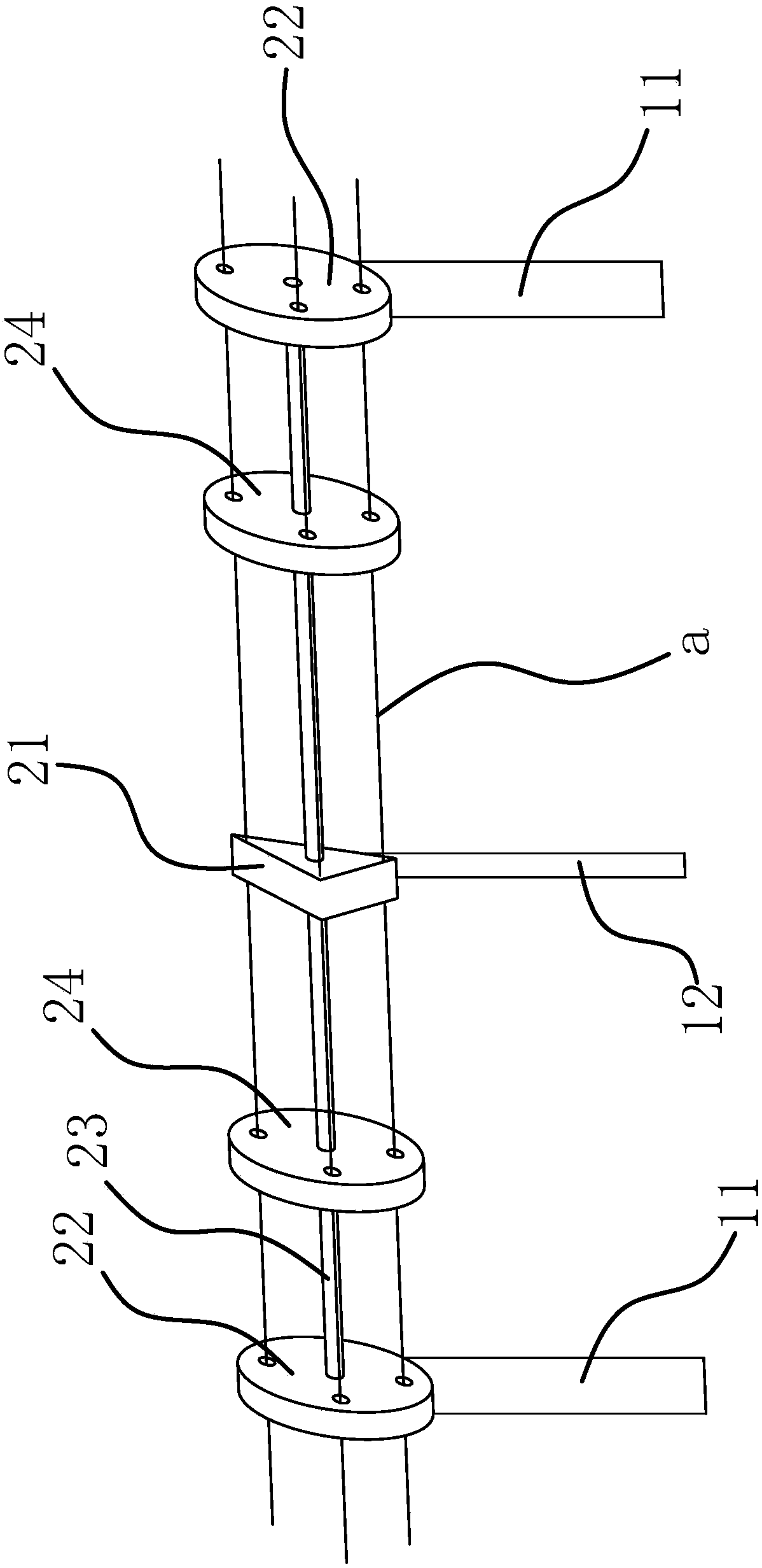
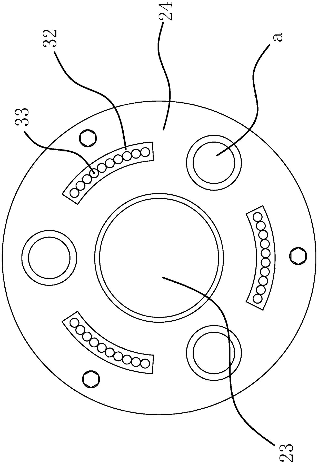
[0031] Such as figure 1 As shown, the high-voltage power distribution system includes three parallel busbars a. The device includes two end support rods 11 and a middle support rod 12. A fixing seat 21 is fixedly arranged on the middle support rod. The three busbars a are all connected to the fixed Seat 21 is fixedly connected, and end support rod 11 is fixedly provided with a circular fixed disk 22, and the middle part of fixed disk 22 is fixedly provided with a connecting shaft 23, and connecting shaft 23 is connected with a rotating disk 24, and the connection between rotating disk 24 and connecting shaft 23 A torsion spring 47 that can drive the rotating disk 24 to rotate relative to the shaft 23 is arranged between them. The busbar a is f...


PUM


Abstract

The invention provides a busbar fixing assembly in a high-voltage power distribution system. The high-voltage power distribution system includes three parallel busbars. The fixing assembly includes two end support rods and a middle support rod, the middle support rod is fixedly provided with a fixing base, and the three busbars are all fixedly connected with the fixing base; a circular fixed discis fixedly arranged on each end support rod, a connecting shaft is fixedly arranged in the middle of each fixed disc and connected with a rotating disc, torsion springs capable of driving the rotatingdiscs to rotate relative to the connecting shaft are arranged between the rotating discs and the connecting shaft, the busbars are all fixedly connected with the fixed discs and the rotating discs, and the rotating discs are located at the sides, closes to the busbar fixing base, of the fixed discs; the fixing base is located in the middle of the space between the two fixed discs, and the rotating discs are located in the middles of the spaces the fixed discs which are matched with the rotating discs and the fixing base; the connecting shaft is also fixedly connected with the fixing base. Thebusbar fixing assembly has the advantages of balanced stress borne by the busbars and the like.

Description

technical field [0001] The invention relates to a detection system for power grid equipment, in particular to a busbar fixing assembly in a high-voltage power distribution system. Background technique [0002] Under the influence of different environments, different climates (such as high temperature and heat, rain, snow and freezing), short-circuit faults in the vicinity of the busbar and busbar hardware faults, the tubular busbars in the operation of the substation move due to thermal expansion and contraction, and the tube mother and the bracket produce Friction will cause the supporting porcelain bottle below to be under greater stress, shorten the service life of the porcelain bottle, and even cause the busbar pillar porcelain bottle to break. [0003] The thermal expansion and contraction of the busbar lead to different lengths, causing the busbar to be concave or over-tensioned, which affects the performance of the busbar and the strength of the busbar fixing device. ...

Claims


Application Information

Patent Timeline
Patent Type & Authority Applications(China)
IPC IPC(8): H02G5/00
CPCH02G5/00
Inventor 陈自球
Owner ELECTRIC POWER RES INST OF GUANGDONG POWER GRID
Why Eureka
Try Eureka