Novel hydraulic strain clamp

A tension-resistant clamp and hydraulic technology, which is applied in the direction of adjusting/maintaining mechanical tension, can solve the problems of poor electrical connection between the drainage clamp and the pipe body, unfavorable long-term stable operation of the power supply line, and affecting the quality of the electrical connection, so as to prevent sand Dust enters the contact surface of the fittings, reduces the duration of acid rain, and has the effect of large contact area of ​​the fittings

Inactive Publication Date: 2018-05-25
STATE GRID SHANDONG ELECTRIC POWER COMPANY WEIFANG POWER SUPPLY +1
View PDF4 Cites 0 Cited by
  • Summary
  • Abstract
  • Description
  • Claims
  • Application Information

AI Technical Summary

Problems solved by technology

The traditional hydraulic tension clamp has a simple structure and is easy to operate. It is widely used in power systems. The disadvantages are: 1. The drainage clamp is only pressed on the pipe body by bolts and relies on the pressing force to realize the drainage clamp. The electrical connection with the pipe body, so there is a problem that the bolts loosen after long-term use, resulting in poor electrical connection between the drainage wire clip and the pipe bod

Method used


Image

  • Novel hydraulic strain clamp
  • Novel hydraulic strain clamp
  • Novel hydraulic strain clamp

Examples


Example Embodiment

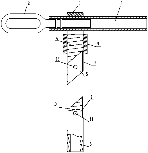
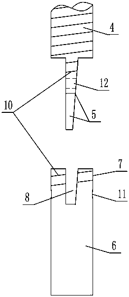
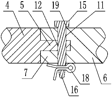
[0033] As shown in the figure, the new hydraulic strain clamp includes a pipe body 1, a steel anchor 2 is inserted at one end of the pipe body 1, and a drainage stud 4 arranged vertically downward is fixed on the outer circumference of the pipe body 1 through a fixing sleeve 3. The lower end surface of the drainage stud is an inclined surface 01 that is inclined to the axis of the drainage stud. The end of the drainage stud 4 is fixed with a vertically arranged insert plate 5, and the insert plate 5 is a metal plate with a parallelogram shape. The plate 5 includes an upper end surface corresponding to the inclined surface 01, a lower end surface 02 facing downwards, a front plate surface 03 and a rear plate surface 04 with the largest area, and a left side which is connected to the arc-shaped outer wall of the drainage stud 4 and extends downward. The arc surface 05 and the right arc surface 06 six board surfaces, the left arc surface and the right arc surface are arc surfaces c...


PUM


Abstract

The invention discloses a novel hydraulic strain clamp. The novel hydraulic strain clamp comprises a pipe body, wherein one end of the pipe body is inserted with a steel anchor. The novel hydraulic strain clamp is characterized in that the outer periphery of the pipe body is fixedly connected with a drainage stud through a fixing sleeve, a plug board is fixedly arranged at a tail end of the drainage stud, a drainage pipe is further comprised, an end portion of the drainage pipe is provided with two clamping boards at an interval, a slot in plugging matching with the plug board is arranged between the two clamping boards, the two clamping boards and the plug board are fixed through a positioning device, the stud is screwed with a nut, and outer side walls of the clamping boards and the plugboard are provided with outer thread corresponding to the nut. The novel hydraulic strain clamp is advantaged in that properties of reasonable structure, rapid connection, large metal fitting contactarea and smaller connection resistance are realized, the antifouling function is further realized, sand and dust can be prevented from entering the metal fitting contact surface, the duration time ofacid rain is reduced, the corrosion and aging degree of metal fittings can be effectively alleviated, and prolongation of service life and prolongation of the maintenance period are facilitated.

Description

technical field [0001] The invention relates to a novel hydraulic tension clamp. Background technique [0002] The hydraulic tension clamp is used to fix the long extended wire to bear the extension tension of the wire in the length direction, and hang the wire to the metal fitting on the tension string or tower. Tension clamps are generally used for corners, connections, and terminal connections in wire laying. Hydraulic tension clamps are generally used in pairs when used in practice. Generally, the tension clamps are set at both ends of the laid wires, which can play the role of stretching the wires. The second function of the strain clamp is to connect and transmit power at both ends of the wire. Generally, the power overhead conductors used in the electric power industry are spiral aluminum-clad steel wires, and the spiral aluminum-clad steel wires have extremely strong tensile strength without concentrated stress. The use of hydraulic tension clamps for wire laying...

Claims


Application Information

Patent Timeline
IPC IPC(8): H02G7/02
CPCH02G7/02
Inventor 孙明星唐立刚王超刘小欧于冬李清华李振东许子涛顾泽林金阿龙
Owner STATE GRID SHANDONG ELECTRIC POWER COMPANY WEIFANG POWER SUPPLY
Why Eureka
Try Eureka